Using Other Surface-Drawing Tools
In the previous example, you used the Edge Surface tool to create a 3D surface. You can also use several other 3D surface commands to generate complex surface shapes easily.
| Tip | All the objects described in this section, along with the meshes described earlier, are actually composites of 3D Faces. This means that you can explode these 3D objects into their component 3D Faces, which in turn can be edited individually. |
Using Two Objects to Define a Surface
The Ruled Surface tool on the Surfaces toolbar draws a surface between two 2D objects, such as a line and an arc, or a polyline and an arc. This command is useful for creating extruded forms that transform from one shape to another along a straight path . Let's see firsthand how the Ruled Surface tool works:
-
On the CD Open the file called Rulesurf.dwg from the companion CD. It looks like the first image in Figure 16.28. This drawing is of a simple half-circle, drawn using a line and an arc. Ignore the diagonal blue line for now; you'll use it in the next exercise.
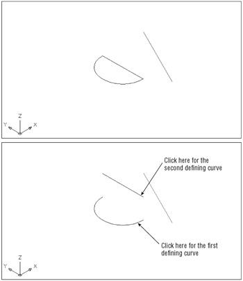
Figure 16.28: Drawing two edges for the Ruled Surface option
Creating a 3D Mesh by Specifying Coordinates If you need to draw a mesh like the one in the previous example, but you want to give exact coordinates for each vertex in the mesh grid, you can use the 3DMesh command. Suppose you have data from a survey of a piece of land; you can use 3DMesh to convert your data into a graphic representation of its topography . Another use of the 3DMesh command is to plot mathematical data to get a graphic representation of a formula.
Because you must enter the coordinate for each vertex in the mesh, 3DMesh is better suited in scripts or AutoLISP programs, in which a list of coordinates can be applied automatically to the 3DMesh command in a sequential order. See Chapter 19 for more information on AutoLISP.
-
Move the line that's currently between the arc endpoints 10 units in the z-axis.
-
 Now you are ready to connect the two objects with a 3D surface. Click the Ruled Surface tool on the Surfaces toolbar or choose Draw Surfaces Ruled Surface.
 -
At the Select first defining curve: prompt, place the cursor toward the right end of the arc and click.
-
At the Select second defining curve: prompt, move the cursor toward the right end of the line and click, as shown in the second image in Figure 16.28. The surface will appear as shown in Figure 16.29.
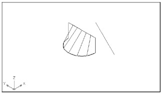
Figure 16.29: The Rulesurf surfaceWarning The position you use to pick the second object will determine how the surface is generated.
The location you use to select the two objects for the ruled surface is important. You selected specific locations on the arc and line so that the ruled surface is generated properly. Had you selected the opposite end of the line, for example, your result would look more like Figure 16.30. Notice that the segments defining the surface cross each other. Picking the defining objects near opposite endpoints causes this crossing effect. The arc was picked near its lower end, and the line was picked toward the top end. At times, you might want this effect.
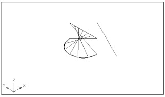
Figure 16.30: The ruled surface redrawn by using different points to select the objects
Extruding an Object Along a Straight Line
The Tabulated Surface tool also uses two objects to draw a 3D surface, but instead of drawing the surface between the objects, the Tabulated Surface tool extrudes one object in a direction defined by a direction vector. The net result is an extruded shape that is the length and direction of the direction vector.
To see what this means firsthand, try the following exercise:
-
While still in the Rulesurf drawing, click the Undo button in the Standard toolbar to restore the drawing to the bottom image of Figure 17.28.
-
 Click the Tabulated Surface tool on the Surface toolbar or choose Draw Surfaces Tabulated Surfaces.
 -
At the Select object for path curve: prompt, click the arc.
-
At the Select object for direction vector: prompt, click the lower end of the blue line farthest to the right. The arc is extruded in the direction of the blue line, as shown in Figure 16.31.
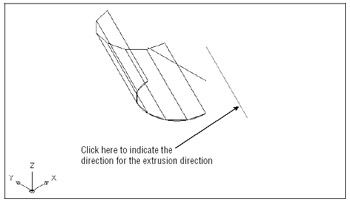
Figure 16.31: Extruding an arc by using a line to indicate the extrusion direction
The direction vector can be any object, but AutoCAD will consider only the object's two endpoints when extruding the path curve. Just as with the Ruled Surface tool, the point at which you select the direction vector object affects the outcome of the extrusion. If you had selected a location near the top of the blue line, the extrusion would have gone in the opposite direction from the exercise.
Because the direction vector can point in any direction, the Tabulated Surface tool enables you to create an extruded shape that is not restricted to a direction perpendicular to the object being extruded.
The path curve defining the shape of the extrusion can be an arc, a circle, a line, or a polyline. You can use a curve-fitted polyline or a spline polyline to create more-complex shapes, as shown in Figure 16.32. There you see a set of objects in the upper left that were created using the Ruled Surface tool. The Tabulated Surface tool and the line in the lower right were used to create the forms in the right side of the figure.
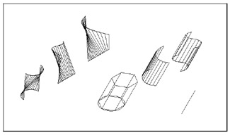
Figure 16.32: Samples of shapes created using the Ruled Surface and Tabulated Surface tools
To increase the number of facets in either the Ruled Surface or Tabulated Surface tools, set the Surftab1 system variable to the number of facets you want.
Extruding a Circular Surface
The Revolved Surface tool enables you to generate circular extrusions quickly. Typical examples are vases or teacups. The following exercise illustrates how you can use the Revolved Surface tool to draw a pitcher. You'll use an existing drawing that has a profile of the pitcher already drawn:
-
On the CD Open the Pitcher.dwg file from the companion CD. This file contains a polyline profile of a pitcher as well as a single line representing the center axis of the pitcher (see the top image in Figure 16.34 later in this chapter). The profile and line have already been rotated to a position that is perpendicular to the WCS. The grid is turned on so you can better visualize the plane of the WCS.
-
 Click the Revolved Surface tool on the Surfaces toolbar or select Draw Surfaces Revolved Surface.
 -
At the Select object to revolve: prompt, click the polyline profile, as shown in the first image in Figure 16.33.
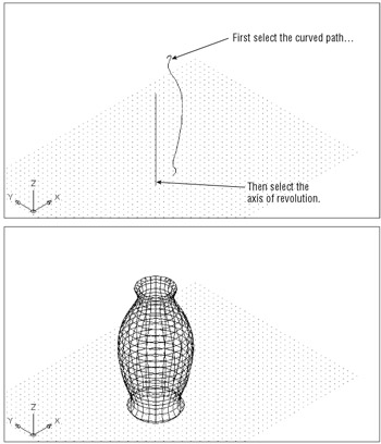
Figure 16.33: Drawing a pitcher by using the Revolved Surface tool -
At the Select object that defines the axis of Revolution: prompt, click near the bottom of the vertical line representing the center of the vase, as shown in the first image in Figure 16.33.
-
At the Specify start angle <0>: prompt, press
 to accept the 0 start angle.
 -
At the Specify included angle (+=ccw, -=cw) <360>: prompt, press
to accept the Full Circle default. The pitcher appears, as shown in the second image in Figure 16.33.
Notice that the pitcher is made up of a faceted mesh, like the mesh that is created by the Edge Surface tool. Just as with the Edge Surface tool, you can set the number of facets in each direction by using the Surftab1 and Surftab2 system variable settings. Both Surftab1 and Surftab2 were already set to 24 in the Pitcher.dwg file, so the pitcher shape should appear fairly smooth.
You might have noticed that in steps 5 and 6 of the previous exercise you have a few options. In step 5, you can specify a start angle. In this case, you accepted the 0 default. Had you entered a different value, 90 for example, the extrusion would have started in the 90 ° position relative to the current WCS. In step 6, you have the option of specifying the angle of the extrusion. Had you entered 180, for example, your result would have been half the pitcher. You can also specify the direction of the extrusion by specifying a negative or positive angle.
EAN: 2147483647
Pages: 261