Marking Divisions on Curves
Perhaps one of the most difficult things to do in manual drafting is to mark regular intervals on a curve. AutoCAD offers the Divide and Measure commands to help you perform this task with speed and accuracy.
| Tip | The Divide and Measure commands are discussed here in conjunction with polylines, but you can use these commands on any object except blocks and text. |
Dividing Objects into Segments of Equal Length
You use the Divide command to divide an object into a specific number of equal segments. For example, suppose you need to mark off the contour you've been working on in this chapter into nine equal segments. One way to do this is to first find the length of the contour by using the List command and then sit down with a pencil and paper to figure out the exact distances between the marks. But there is another, easier way.
The Divide command places a set of point objects on a line, an arc, a circle, or a polyline, marking off exact divisions. This following exercise shows how it works:
-
On the CD Open the 13a-divd.dwg file from the companion CD. This file is similar to the one you have been working with in the previous exercises.
-
Choose Draw Point Divide or type Div
 .
. -
At the Select object to divide: prompt, pick the spline contour line that shows Xs in Figure 13.25.
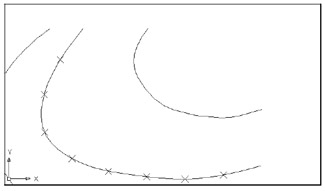
Figure 13.25: Using the Divide command on a polyline -
The Enter number of segments or [Block]: prompt that appears next is asking for the number of divisions you want on the selected object. Enter 9
. The command prompt now returns, and it appears that nothing has happened . But AutoCAD has placed several points on the contour that indicate the locations of the nine divisions you requested . To see these points more clearly, follow these steps:
-
Choose Format Point Style to open the Point Style dialog box.
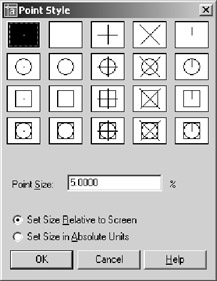
-
Click the X point style in the upper-right side of the dialog box, click the Set Size Relative To Screen radio button, and then click OK.
-
If the Xs don't appear, choose View Regen or enter Re
. A set of Xs appears, showing the nine divisions (see Figure 13.25). Tip You can also change the point style by changing the Pdmode system variable. When Pdmode is set to 3, the point appears as an X. See Appendix C for more information on Pdmode.
The Divide command uses point objects to indicate the division points. You create point objects by using the Point command; they usually appear as dots. Unfortunately, such points are nearly invisible when placed on top of other objects. But, as you have seen, you can alter their shape by using the Point Style dialog box. You can use these X points to place objects or references to break the object being divided. (The Divide command does not actually cut the object into smaller divisions.)
| Tip | If you are in a hurry and you don't want to bother changing the shape of the point objects, you can do the following: Set the Running Osnaps to Node. Then, when you are in the Point Selection mode, move the cursor over the divided curve. When the cursor gets close to a point object, the Node Osnap marker appears. |
Dividing Objects into Specified Lengths
The Measure command acts just like Divide; however, instead of dividing an object into segments of equal length, the Measure command marks intervals of a specified distance along an object. For example, suppose you need to mark some segments exactly 5 ¢ apart along the contour. Try the following exercise to see how the Measure command is used to accomplish this task:
-
Erase the X-shaped point objects.
-
Choose Draw Point Measure or type Me
. -
At the Select object to measure: prompt, pick the contour at a point closest to its lower endpoint. I'll explain shortly why this is important.
-
At the Specify length of segment or [Block]: prompt, enter 60
. The X points appear at the specified distance. -
Exit this file.
Tip The Measure command is AutoCAD's equivalent of the divider tool in manual drafting. A divider is a V-shaped instrument, similar to a compass, used to mark off regular intervals along a curve or line.
Bear in mind that the point you pick on the object to be measured determines where the Measure command begins measuring. In the previous exercise, for example, you picked the contour near its bottom endpoint. If you picked the top of the contour, the results would be different because the measurement would start at the top, not the bottom.
| |
You can also use the Block option under the Divide and Measure commands to place blocks at regular intervals along a line, a polyline, or an arc. Here's how to use blocks as markers:
-
Be sure the block you want to use is part of the current drawing file.
-
Start either the Divide or Measure command.
-
At the Specify length of segment or [Block]: prompt, enter B
. -
At the Enter name of block to insert: prompt, enter the name of a block.
-
At the Align Block with Object? [Yes/No]: prompt, press
if you want the blocks to follow the alignment of the selected object. (Entering N inserts each block at a 0 ° angle.) -
At the Enter the number of Segments: prompt, enter the number of segments. The blocks appear at regular intervals on the selected object.
One example of using Divide's or Measure's Block option is to place a row of sinks equally spaced along a wall. Or you might use this technique to make multiple copies of an object along an irregular path defined by a polyline. In civil engineering projects, you can indicate a fence line by using Divide or Measure to place Xs along a polyline.
| |
EAN: 2147483647
Pages: 261