Using Advanced Tools: Filter, Quick Select, and the Calculator
Two other tools are extremely useful in your day-to-day work with AutoCAD: selection filters and the Calculator. I have saved the discussion of these tools until the end of this chapter because you don't really need them until you've become accustomed to the way AutoCAD works. Chances are you've already experimented with some of the AutoCAD menu options not yet discussed in the tutorial. Many of the pull-down menu options and their functions are self-explanatory. Selection filters and the Calculator, however, do not appear in any of the menus and require some further explanation.
Let's start with selection filters. There are actually two selection-filtering tools in AutoCAD. The Quick Select tool offers a quick way to locate objects based on their properties. The Filter tool lets you select objects based on a more complex set of criteria.
Filtering Selections
Suppose you need to isolate just the walls of your drawing in a separate file. One way to do this is to turn off all the layers except the Wall layer. You can then use the Wblock command and select the remaining walls, using a window to write the wall information to a file. Filters can simplify this operation by enabling you to select groups of objects based on their properties.
Follow these steps to select objects based on their layer assignment:
-
Open the Unit file.
-
Type w
 to start the Wblock command. Then, in the Write Block dialog box, enter Unitwall in the File Name input box.
 -
Make sure the Object radio button is selected in the top of the dialog box, and then click the Select Objects button in the Objects group . The dialog box disappears to enable you to select objects.
-
At the Object Selection: prompt, type ¢ Filter
to open the Object Selection Filters dialog box. 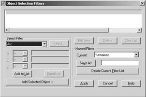
-
Open the drop-down list in the Select Filter group.
-
Scroll down the list, and find and highlight the Layer option.
-
Click the Select button next to the drop-down list to display a list of layers. Then highlight Wall and click OK.
-
In the Object Selection Filters dialog box, click the Add To List button toward the bottom of the Select Filter group to add Layer = Wall to the list box.
-
Click Apply to close the Object Selection Filters dialog box.
-
Type all
to select everything in the drawing. Only the objects assigned to the Wall layer are selected. You'll see a message in the Command window indicating how many objects were found and how many were filtered out. -
Press
and you'll see the message Exiting Filtered selection Resuming WBLOCK command- Select objects: 14 found . -
Press
again to complete the Wblock command. All the walls are written out to a file called Unitwall . -
After reviewing the results of the exercise, type U
or click the Undo button in the Standard toolbar to undo the Wblock command.
In this exercise, you filtered out a layer by using the Wblock command. After a filter is designated, you then select the group of objects you want AutoCAD to filter through. AutoCAD finds the objects that match the filter requirements and passes those objects to the current command.
As you've seen from the previous exercise, you can choose from many options in this utility. Let's take a closer look.
Working with the Object Selection Filters Dialog Box
To use the Object Selection Filters dialog box, first select the criteria for filtering from the pull-down list. If the criterion you select is a named item (layer, line type, color , or block), you can then click the Select button to choose specific items from a list. If there is only one choice, the Select button is dimmed.
After you've determined what to filter, you must add it to the list by clicking the Add To List button. The filter criterion then appears in the list box at the top of the Object Selection Filters dialog box and you can apply that criterion to your current command or to a later command. AutoCAD remembers your filter settings, so if you need to reselect a filtered selection set, you don't have to redefine your filter criteria.
Saving Filter Criteria
If you prefer, you can preselect filter criteria. Then, at any Select objects: prompt, you can click Selection Filters on the toolbar (or type ¢ Filter ![]() ), highlight the appropriate filter criteria in the list box, and click Apply. The specifications in the Object Selection Filters dialog box remain in place for the duration of the current editing session.
), highlight the appropriate filter criteria in the list box, and click Apply. The specifications in the Object Selection Filters dialog box remain in place for the duration of the current editing session.
You can also save a set of criteria by entering a name in the input box next to the Save As button and then clicking the button. The criteria list data is saved in a file called Filter.nfl . You can then access the criteria list at any time by opening the Current drop-down list and choosing the name of the saved criteria list.
Filtering Objects by Location
Notice the X, Y, and Z drop-down lists just below the main Select Filter drop-down list in the Object Selection Filters dialog box. These lists become accessible when you select a criterion that describes a geometry or a coordinate (such as an arc's radius or center point). You can use these lists to define filter selections even more specifically , using greater than (>), less than (<), equal to (=), or not equal to (!=) comparisons (called relational operators ).
For example, suppose you want to grab all the circles whose radii are greater than 4.0 units. To do this, choose Circle Radius from the Select Filter drop-down list. Then in the X list, select >. Enter 4.0 in the input box to the right of the X list, and click Add To List. You see the item
Circle Radius > 4.0000
added to the list box at the top of the dialog box. You used the > operator to indicate a circle radius greater than 4.0 units.
Creating Complex Selection Sets
At times you'll want to create a specific filter list. For instance, say you need to filter out all the door blocks on the layer Floor2 and all arcs with a radius equal to 1. To do this, you use the grouping operators found at the bottom of the Select Filter drop-down list. You'll need to build a list as follows :
** Begin OR
** Begin AND
Entity = Block
Layer = Floor2
** End AND
** Begin AND
Entity = Arc
Arc Radius = 1.0000
** End AND
** End OR
Notice that the Begin and End operators are balanced; that is, for every Begin OR or Begin AND , there is an End OR or End AND .
This list might look rather simple, but it can get confusing. If criteria are bounded by the AND grouping operators, the objects must fulfill both criteria before they are selected. If criteria are bounded by the OR grouping operators, the objects fulfilling either criteria will be selected.
Here are the steps to build the previous list:
-
In the Select Filter drop-down list, choose **Begin OR and then click Add To List. Then do the same for **Begin AND .
-
Click Block in the Select Filter drop-down list and then click Add To List.
-
For the layer, click Layer from the Select Filter drop-down list. Then click Select, choose the layer name, and click Add To List.
-
In the Select Filter drop-down list, choose **End AND and then click Add To List. Then do the same for **Begin AND .
-
Select Arc from the Select Filter drop-down list and click Add To List.
-
Select Arc Radius from the Select Filter list, and enter 1.0 in the input box next to the X drop-down list. Be sure the equal sign (=) shows in the X drop-down list and then click Add To List.
-
Choose **End AND and click Add To List. Then do the same for **End OR .
If you make an error in any step, simply highlight the item, select an item to replace it, and click the Substitute button instead of the Add To List button. If you need to only change a value, click Edit Item near the center of the dialog box.
Using Quick Select
The Filter command offers a lot of power in isolating specific types of objects, but in many situations, you might not need such an elaborate tool. The Qselect command can filter your selection based on the object properties, which are more common filter criteria. To access the Qselect command, choose Tools Quick Select, or right-click the drawing area when no command is active and choose Quick Select from the shortcut menu to open the Quick Select dialog box.
Quick Select is also offered as an option on a few dialog boxes. Try using the Wblock command again, this time using the Quick Select option offered in its dialog box:
-
With the Unit file open, type W
to start the Wblock command, and then in the Write Block dialog box, enter Unitwall2 in the File Name input box. -
 Make sure the Object radio button is selected in the top of the dialog box. Then click the Quick Select button to the right of the Select Objects button in the Objects group to open the Quick Select dialog box.
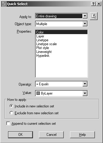
-
Select Layer from the Properties list.
-
Select Wall from the Value drop-down list near the bottom of the dialog box.
-
Click the Select Objects button in the upper-right corner of the dialog box. The dialog box disappears to enable you to select objects.
-
Select the entire drawing by using a window and then press
to finish your selection. The Quick Select dialog box returns. -
Click OK, and then click OK in the Write Block dialog box. The walls disappear, indicating that they have been written to a file.
The Qselect command selects objects based on the object's properties, as shown in the Properties list box. You can apply the selection criteria based on the entire drawing, or you can use the Select Objects button in the upper-right corner of the dialog box to isolate a set of objects to which you want to apply the selection criteria.
In the previous exercise, you used Quick Select from within another dialog box. As mentioned earlier, you can also use Quick Select by choosing Tools Quick Select or by right-clicking the drawing area when no command is active and choosing Quick Select from the shortcut menu. Quick Select then makes use of the Noun/Verb selection method so you select objects using Quick Select first, and then you apply editing commands to the selected objects.
| Tip | If you want to use Quick Select with a command that does not allow the Noun/Verb selection method, you can select objects by using Quick Select, start the command you want to use, and then use the Previous Selection option. |
Here is a description of the Quick Select dialog box options:
Apply To Lets you determine the set of objects to which you want to apply the Quick Select filters. The default is the entire drawing, but you can use the Select Objects button to select a set of objects. If a set of objects has been selected before issuing the Quick Select command, you also see the Current Selection option in the Apply To drop-down list.
Object Type Lets you limit the filter to specific types of objects such as lines, arcs, circles, and so on. The Multiple option lets you filter your selection from all the objects in the drawing regardless of its type.
Properties After you select an object type, you can then select the property of the object type you want to filter. The Properties list changes to reflect the properties that are available to be filtered.
Operator Offers a set of criteria to apply to the property you select in the Properties list to make your selection. You can select objects that are equal to or not equal to the criteria you select in the Object Type and Properties lists. Depending on the property you select, you also might have the option to select objects that are greater than or less than a given property value. For example, you can select all lines whose X coordinate is less than 5 by choosing Line from the Object Type drop- down list and Start X from the Properties list. You then select < Less Than from the Operator drop-down list and enter 5 in the Value input box.
Value Displays the values of the property you select in the Properties list. For example, if you select Layer from the Properties list, the Value option lists all the layers available.
How To Apply Lets you determine whether to include or exclude the filtered objects in a new selection set.
Append To Current Selection Set Lets you append the filtered objects to an existing selection set or create an entirely new selection set.
Finding Geometry with the Calculator
ACAD only Another useful AutoCAD tool is the Geometry Calculator. Like most calculators , it adds, subtracts, divides, and multiplies. If you enter an arithmetic expression such as 1 + 2, the calculator returns 3. This is useful for doing math on the fly, but the Calculator does much more than arithmetic, as you will see in the next examples.
Finding the Midpoint between Two Points
One of the most common questions heard from AutoCAD users is, How can I locate a point midway between two objects? You can draw a construction line between the two objects and then use the Midpoint override to select the midpoint of the construction line. The Calculator offers another method that doesn't require drawing additional objects.
In the following exercise, you start a line midway between the center of an arc and the endpoint of another line. Draw a line and an arc and try this:
-
Start the Line command, and at the Specify first point: prompt, type ¢ Cal
. -
At the >> Expression: prompt, enter (end + cen)/2
. -
At the >> Select entity for END snap: prompt, the cursor turns into a square. Place the square on the endpoint of a line and click it.
-
At the >> Select entity for CEN snap: prompt, click an arc. The line starts midway between the arc's center and the endpoint of the line.
Tip If typing the Calculator expressions seems a bit too cumbersome to do on a regular basis, you can create a toolbar macro to simplify the Calculator's use. See Chapter 20 for more on customizing toolbars .
Using Osnap Modes in Calculator Expressions
In the previous exercise, you used Osnap modes as part of arithmetic expressions. The Calculator treats them as temporary placeholders for point coordinates until you actually pick the points (at the prompts shown in steps 3 and 4).
The expression
(end + cen)/2
finds the average of two values. In this case, the values are coordinates, so the average is the midpoint between the two coordinates. You can take this one step further and find the centroid of a triangle by using this expression:
(end + end + end)/3
Note that only the first three letters of the Osnap mode are entered in Calculator expressions. Table 12.1 shows what to enter in an expression for Osnap modes.
Select circle, arc or polyline segment for RAD function:
| Calculator Osnap | Meaning |
|---|---|
| End | Endpoint |
| Ins | Insert |
| Int | Intersection |
| Mid | Midpoint |
| Cen | Center |
| Nea | Nearest |
| Nod | Node |
| Qua | Quadrant |
| Per | Perpendicular |
| Tan | Tangent |
| Rad | Radius of object |
| Cur | Cursor pick |
You can then select an arc, a polyline arc segment, or a circle, and its radius is used in place of Rad in the expression.
The other item, Cur, prompts you for a point. Instead of looking for specific geometry on an object, it just locates a point. You could have used Cur in the previous exercise in place of the End and Cen modes to create a more general-purpose midpoint locator, as in the following form:
(cur + cur)/2
Because AutoCAD does not provide a specific tool to select a point midway between two other points, the form shown here would be useful as a custom toolbar macro. You'll learn how to create macros in Chapter 20.
Finding a Point Relative to Another Point
Another common task in AutoCAD is starting a line at a relative distance from another line. The following steps describe how to use the Calculator to start a line from a point that is 2.5 ² in the x-axis and 5.0 ² in the y-axis from the endpoint of another line:
-
Start the Line command. At the First point: prompt, enter ¢ Cal
. -
At the >> Expression: prompt, enter end + [2.5,5.0]
. -
At the >> Select entity for END snap: prompt, pick the endpoint. The line starts from the desired location.
In this example, you used the Endpoint Osnap mode to indicate a point of reference. This is added to Cartesian coordinates in square brackets, describing the distance and direction from the reference point. You could have entered any coordinate value within the square brackets. You also could have entered a polar coordinate in place of the Cartesian coordinate, as in the following: end + [5.59<63] . You don't have to include an @, because the Calculator assumes you want to add the coordinate to the one indicated by the Endpoint Osnap mode. Also, it's not necessary to include every coordinate in the square brackets. For example, to indicate a displacement in only one axis, you can leave out a value for the other two coordinates, as in the following examples:
[4,5] = [4,5,0] [,1] = [0,1,0]
[,,2] = [0,0,2]
Adding Feet and Inch Distances on the Fly
If you use feet and inches, one of the more frustrating situations you might have run across is having to stop in the middle of a command to find the sum of two or more distances. Say you start the Move command, select your objects, and pick a base point. You then realize you don't know the distance for the move, but you do know that the distance is the sum of two values ” unfortunately , one value is in feet and the other is in inches. Usually in this situation you would have to reach for pen and paper (or, if you have one, a feet-and-inches calculator), figure out the distance, and then return to your computer to finish the task. AutoCAD's Geometry Calculator puts an end to this runaround. The following steps show you what to do if you want to move a set of objects a distance that is the sum of 12 ¢ -6 5 / 8 ² and 115 ¾ ² :
-
Issue the Move command, select objects, and pick a base point.
-
At the Second point: prompt, start the Calculator.
-
At the >> Expression: prompt, enter [@12 ¢ 6 “ 5 / 8 ² + 115 “ ¾ ² < 45] . Then press
, and the objects move into place at the proper distance. Warning You must always enter an inch symbol ( ² ) when indicating inches in the Calculator.
In this example, you are mixing inches and feet, which under normal circumstances is a time- consuming calculation. Notice that the feet-and-inches format follows the standard AutoCAD syntax (no space between the feet and inch values). The coordinate value in square brackets can have any number of operators and values, as in the following:
[@4 * (22 + 15) - (23.3 / 12) + 1 < 13 + 17]
This expression demonstrates that you can also apply operators to angle values.
Guidelines for Working with the Calculator
You might be noticing some patterns in the way expressions are formatted for the Calculator. Here are some guidelines to remember:
-
Coordinates are enclosed in square brackets.
-
Nested or grouped expressions are enclosed in parentheses.
-
Operators are placed between values, as in simple math equations.
-
Object snaps can be used in place of coordinate values.
| Operator/Function | What It Does | Example |
|---|---|---|
| + or “ | Add or subtract numbers or vectors | 2 “ 1 = 1 |
| [a,b,c] + [x,y,z] = [a+x, b+y, c+z] | ||
| * or / | Multiply or divide numbers or vectors | 2 * 4.2 = 8.4 |
| a*[x,y,z] = [a*x, a*y, a*z] | ||
| ^ | Exponentiation of a number | 3^2 = 9 |
| sin | Sine of angle | sin (45) = 0.707107 |
| cos | Cosine of angle | cos (30) = 0.866025 |
| tang | Tangent of angle | tang (30) = 0.57735 |
| asin | Arcsine of a real number | asin (0.707107) = 45.0 |
| acos | Arccosine of a real number | acos (0.866025) = 30.0 |
| atan | Arctangent of a real number | atan (0.57735) = 30.0 |
| ln | Natural log | ln (2) = 0.693147 |
| log | Base-10 log | log (2) = 0.30103 |
| exp | Natural exponent | exp (2) = 7.38906 |
| exp10 | Base-10 exponent | exp10 (2) = 100 |
| sqr | Square of number | sqr (9) = 81.0 |
| abs | Absolute value | abs ( “3.4) = 3.4 |
| round | Round to nearest integer | round (3.6) = 4 |
| trunc | Drop decimal portion of real number | trunc (3.6) = 3 |
| r2d | Convert radians to degrees | r2d (1.5708) = 90.0002 |
| d2r | Convert degrees to radians | d2r (90) = 1.5708 |
| pi | The constant pi | 3.14159 |
The Geometry Calculator is capable of much more than the typical uses you've seen here. A description of its full capabilities extends beyond the scope of this text. Still, the processes described in this section will be helpful as you use AutoCAD. If you want to know more about the Calculator, consult the AutoCAD Help User Documentation (choose Help Help).
EAN: 2147483647
Pages: 261