Tracing a Drawing
The most common way to enter a hand-drafted drawing into AutoCAD is tracing with a digitizer . If you are working with a large drawing and you have a small tablet, you might have to cut the drawing into pieces that your tablet can manage, trace each piece, and then assemble the completed pieces into the large drawing. However, the best solution is a large tablet.The following exercises are designed for a 4 ² 5 ² (10 cm 12.7 cm) or larger tablet. The sample drawings are small enough to fit completely on this size tablet. You can use either a stylus or a puck to trace them, but the stylus provides the most natural feel because it is shaped like a pen. A puck has crosshairs that you have to center on the line you want to trace, and this requires a bit more dexterity.
| Tip | If you don't have a digitizing tablet, you can use scaling to enter the utility room drawing used in this section's tracing exercise. (You will insert the utility room into your apartment building plan in Chapter 12.) |
Reconfiguring the Tablet for Tracing
When you first installed AutoCAD, you configured the tablet to use most of its active drawing area for AutoCAD's menu template (see Appendix A for more information). Because you will need the tablet's entire drawing area to trace this drawing, you now need to reconfigure the tablet to eliminate the menu. Otherwise, you won't be able to pick points on the drawing outside the 4 ² 3 ² (10 cm 7.6 cm) screen pointing area AutoCAD normally uses (see Figure 11.1).
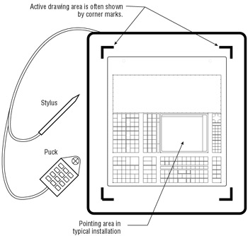
Figure 11.1: The tablet's active drawing area
| Tip | You can save several AutoCAD configurations that can be easily set by using the Options dialog box. |
Here are the steps to follow:
-
Start AutoCAD and create a new file called Utility .
-
Set up the file as an architectural drawing with a ¼ ² = 1 ¢ scale on an 8 ½ ² 11 ² sheet (limits set to 0,0 for the lower-left corner and 528,408 for the upper-right corner). Metric users should set up their drawing at a 1:50 scale on an A4 size sheet. (Limits for metric users should be 0,0 for the lower-left corner and 1480,1050 for the upper-right corner.)
-
Choose Tools Tablet Configure or type Ta
 CFG .
CFG . -
At the Enter number of tablet menus desired (0-4): prompt, enter
. Warning When selecting points on the tablet, take care not to accidentally press the pick button twice, because this will give you erroneous results. Many tablets have sensitive pick buttons that can cause problems when you are selecting points.

Tracing with Tablets If you're willing to try the latest technology, another option is a tablet PC. These are portable notebook size PCs that use a stylus as an input device. With a Tablet PC you could potentially trace a drawing directly onto the AutoCAD drawing area, as if you were tracing right over the monitor. Some computer monitor manufactures also offer hand held LCD monitors that use pens for input. These monitors are a kind of hybrid between a tablet PC and desktop PC, since they are really just a monitor with a tablet like interface.
Autodesk also offers Architectural Studio, which is a program designed to take full advantage of a tablet PC special characteristics. Architectural Studio is designed to work in concert with AutoCAD and Architectural Desktop, a popular add-on to AutoCAD. It lets you sketch ideas using a pencil and tracking paper metaphor, then transfer your sketches into AutoCAD.
-
At the Do you want to respecify the Fixed Screen Pointing Area?: prompt, enter Y
. -
At the Digitize lower left corner of screen pointing area: prompt, pick the lower-left corner of the tablet's active drawing area.
Tip On some tablets, a light shows you the active area; other tablets use a permanent mark, such as a corner mark. Auto- CAD won't do anything until you have picked a point, so you don't have to worry about picking a point outside this area.
-
At the Digitize upper right corner of screen pointing area: prompt, pick the upper- right corner.
-
At the Do you want to specify the Floating Screen pointing area <N>: prompt, press
.
Now as you move your stylus or puck, you'll notice a difference in the relationship between your hand movement and the screen cursor. The cursor moves more slowly and is active over more of the tablet surface.
Calibrating the Tablet for Your Drawing
Now make a photocopy of Figure 11.2, which represents a hand-drafted drawing of a utility room for your apartment building. Place the photocopied drawing on your tablet so that it is aligned with the tablet and completely within the tablet's active drawing area (see Figure 11.3).
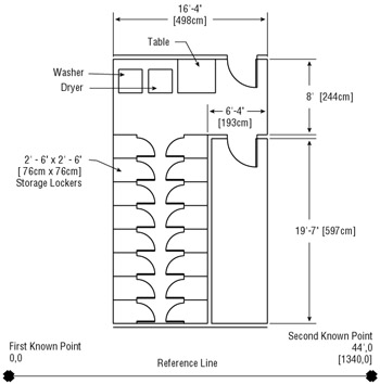
Figure 11.2: The utility room drawing
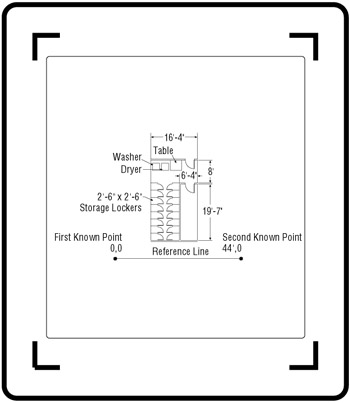
Figure 11.3: The drawing placed on the tablet
Before you can trace anything into your computer, you must calibrate your tablet. This means you must provide some points of reference so AutoCAD can know how distances on the tablet relate to distances in the drawing editor. For example, you might want to trace a drawing that was created at a scale of 1 / 8 ² = 1 ¢ -0 ² . You will have to show AutoCAD two specific points on this drawing, as well as where those two points should appear in the drawing editor. To do this, use the Tablet command's Cal option.
| Tip | When you calibrate a tablet, you are setting ratios for AutoCAD ”for example, 2 ² on your tablet equals 16 ¢ in the drawing editor. |
-
Choose Tools Tablet Calibrate, or enter Tablet
Cal at the command prompt. -
The prompt Digitize point #1: appears, asking you to pick the first point for which you know the absolute coordinates. Pick the X on the left end of the reference line.
-
At the Enter coordinates for point #1: prompt, enter 0,0
. This tells AutoCAD that the point you just picked is equivalent to the coordinate 0,0 in your drawing editor. -
Next , the Digitize point #2: prompt asks you to pick another point for which you know the coordinates. Pick the X on the right end of the reference line.
-
At the Enter coordinates for point #2: prompt, enter 44 ¢ ,0
. Metric users should enter 1340,0 . -
At the Digitize point #3 (or RETURN to end): prompt, press
. The tablet is now calibrated.
The word TABLET appears on the status bar to tell you that you are in Tablet mode. In this mode, you can trace the drawing, but you cannot access the menus in Windows with some digitizers. (Check your digitizer manual for further information.) If you want to choose a menu item, you must toggle the Tablet mode off by pressing the F4 function key. Or you can enter commands through the keyboard. (If you need some reminders of the keyboard commands, type Help ![]() , and click Commands in the Help dialog box to get a list.)
, and click Commands in the Help dialog box to get a list.)
Tracing Lines from a Drawing
Now you are ready to trace the utility room. If you don't have a digitizer, you can skip this exercise. A traced file is included on the companion CD that you can use for later exercises. Here are the steps:
-
Make sure the Ortho and Polar buttons are off in the status bar.
-
Click the Line tool on the Draw toolbar or type L
. -
Trace the outline of all the walls except the storage lockers.
-
Add the doors by inserting the Door file at the appropriate points and then mirroring them. The doors might not fit exactly, but you'll get a chance to make adjustments later.
-
Trace the washer and, because the washer and dryer are the same size, copy the washer over to the position of the dryer.
Tip After a tablet has been calibrated, you can trace your drawing from the tablet, even if the area you are tracing is not displayed in the drawing editor.
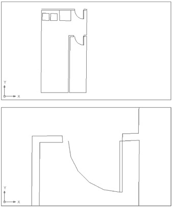
Figure 11.4: The traced drawing and a close-up of the door
| |
In step 6 of the previous exercise, you bypassed the prompt that offered you the chance to calibrate a third point. In fact, you can calibrate as many as 31 points. Why would anyone want to calibrate so many points? Often the drawing or photograph you are trying to trace will be distorted in one direction or another. For example, blueline prints are usually stretched in one direction because of the way prints are rolled through a print machine.
You can compensate for distortions by specifying several known points during your calibration. For example, you could include a vertical distance on the utility room drawing to indicate a distance in the yaxis. You could then pick that distance and calibrate its point. AutoCAD would then have a point of reference for the y distance as well as the x distance. If you calibrate only two points, as you did in the previous exercise, AutoCAD will scale x and y distances equally. Calibrating three points causes AutoCAD to scale x and y distances separately, making adjustments for each axis based on their respective calibration points.
Now suppose you want to trace a perspective view of a building, but you want to "flatten"the perspective so that all the lines are parallel. You can calibrate the four corners of the building's facade to stretch out the narrow end of the perspective view to be parallel with the wide end. This is a limited form of what cartographers call rubber-sheeting, in which various areas of the tablet are stretched by specific scale factors.
When you select more than two points for calibration, you will get a message similar to that shown here. Let's take a look at the parts of this message.
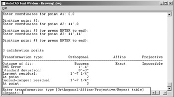
In the Text window, you see the labels Orthogonal, Affine, and Projective. These are the three major types of calibrations, or transformations. The orthogonal transformation scales the x-axis and y-axis by using the same values. Affine transformation scales the x-axis and y-axis separately and requires at least three points. How the projective transformation stretches the tablet coordinates depends on where you are on the tablet. It requires at least four calibration points.
For each transformation type you will see the Outcome Of Fit: either Success, Exact, or Impossible. This tells you whether any of these transformation types are available to you. Because this example shows what you see when you pick three points, you get Impossible for the projective transformation.
The far-left column tells you what is shown in each of the other three columns .
Finally, the prompt at the bottom of the screen lets you select which transformation type to use. If you calibrate four or more points, the projective transformation is added to the prompt. The Repeat Table option simply refreshes the table.
Take care when you calibrate points on your tablet. Here are some tips:
-
Use only known calibration points.
-
Try to locate calibration points that cover a large area of your image.
-
Don't get carried away. Try to limit calibration points to those necessary to get the job done.
| |
Cleaning Up a Traced Drawing
On the CD In this section, you'll reposition a door jamb, straighten some lines, adjust a dimension, and add the storage lockers to the utility room. If you didn't have a chance to digitize your own Utility file, use the file 11a-util.dwg from the companion CD to do the following exercises.
Moving the End of a Wall
-
Enlarge your view so it looks similar to the second image in Figure 11.4.
-
Pick a crossing window, enclosing the door jamb to be moved (see the top image in Figure 11.5).
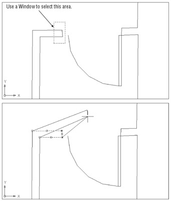
Figure 11.5: Use a Window to select this area. -
Click one of the grips at the end of the wall and then Shift+click the other grip. You should have two hot grips at the door jamb.
-
Click the lower of the two hot grips and drag the corner away to see what happens (see the bottom image in Figure 11.5).
-
Use the Endpoint Osnap to pick the endpoint of the arc. The jamb repositions itself, and all the lines follow (see Figure 11.6).
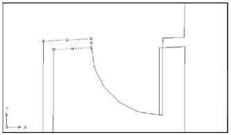
Figure 11.6: The repositioned door jambTip If AutoCAD doesn't respond in the way described in this section, make sure the Noun/Verb selection setting and the Grips feature are both turned on.
Straightening Lines
Another problem in this drawing is that some of the lines are not orthogonal. To straighten them, you use the Change command, together with the Ortho mode. In the following exercise, you'll use the Change command keyboard shortcut:
-
Press the Esc key to clear any active grip selections.
-
Toggle the Ortho mode on.
-
Type “Ch
at the command prompt to start this operation. Make sure you include the minus sign. -
At the Object selection: prompt, pick the four lines representing the walls just left of the door, and press
to confirm your selection. -
At the Specify change point or [Properties]: prompt, click the corner where the two walls meet.
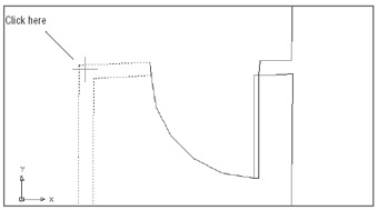
The four lines straighten out, as shown in Figure 11.7.
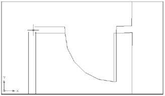
Figure 11.7: The lines after using the Change Point option of the Change command -
After the lines have been straightened, use the Fillet tool in the Modify toolbar to join the corners. You can also choose Modify Fillet Fillet.
Warning The Change command's Change Point option changes the location of the endpoint closest to the new point location. This can cause erroneous results when you are trying to modify groups of lines.
As you have just seen, you can use the Change command to quickly straighten a set of lines. When used carefully , this command can be a real time-saver.
| Warning | Be aware that the Change command moves the nearest endpoints of selected lines to the new location. This can cause unpredictable results in some situations (see Figure 11.9 later in this chapter). Note that the Change command does not affect polyline line segments. |
In addition to straightening lines, you can use the Change command to align a set of lines to another line. For example, when you combine Change with the Perpendicular Osnap, you can align several lines at a perpendicular angle to another line. However, this works only with the Ortho mode on.
You also can extend several lines to be perpendicular to a non-orthogonal line. To do so, you must rotate the cursor to that line's angle (see the top image in Figure 11.8). To rotate the cursor, you can use the Snapang system variable or you can use the Snap Angle input box in the Drawing Aids dialog box (choose Tools Drawing Aids). Then use the process just described to extend or shorten the other lines (see the bottom image in Figure 11.8).
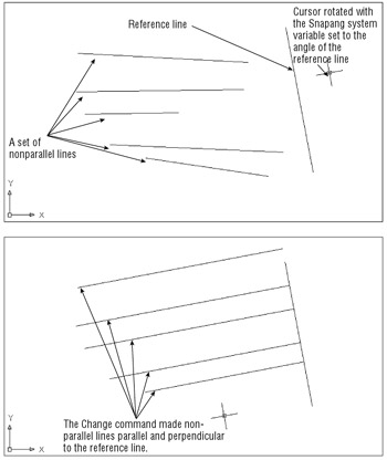
Figure 11.8: You can use the Change command to quickly straighten a set of nonparallel lines and to align their endpoints to another reference line.
When changing several lines to be perpendicular to another line, you must carefully choose the new endpoint location. Figure 11.9 shows what happens to the same line shown in the top image in Figure 11.8 when a perpendicular reference is placed in the middle of the set of lines. Some lines are straightened to a perpendicular orientation, while others have the wrong endpoints aligned with the reference line.
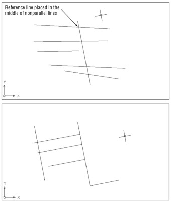
Figure 11.9: The results of the Change command can be unpredictable if the endpoint location is too close to the lines being changed.
Before moving on to the next section, use the Change command to straighten the other lines in your drawing. Start by straightening the corner to the right of the door in Figure 11.7, earlier in this chapter:
-
Issue the Change command again.
-
Select the four lines that represent the walls to the right of the door and then press
. -
Click a point near the corner.
-
Chances are, the two vertical lines are not aligned. Move the top line so that it aligns with the lower one. You can use the Perpendicular Osnap to help with the alignment.
-
Use the Change command on each of the other corners until all the walls have been straightened. You can also use Change in a similar way to straighten the door jambs.
-
After you've straightened the lines, use the Fillet tool on the Modify toolbar to join the corners end to end.
Tip When you confirm your selection to the Change command in step 4, you have the option to press P
for the Properties option. This option lets you change the color , elevation, layer, line type, line-type scale, line weight, and thickness of the selected object. It can be especially helpful in 3D work when you want to set the elevation of several objects to the same elevation. Tip When using the Fillet tool to join lines, you can issue the Fillet command, type C
, and enclose the two lines you want to fillet with a crossing window.
Adjusting the Room Size
The overall interior dimension of the original utility room drawing is 16 ¢ -4 ² 28 ¢ -0 ² . Chances are that the dimensions of the drawing you traced will vary somewhat from these. You will need to adjust your drawing to fit these dimensions:
-
Draw a horizontal line 16 ¢ -4 ² long (498 cm for metric users) from the left wall; then draw a vertical line 28 ¢ long (856.6 cm for metric users) from the bottom wall line, as shown in Figure 11.10.
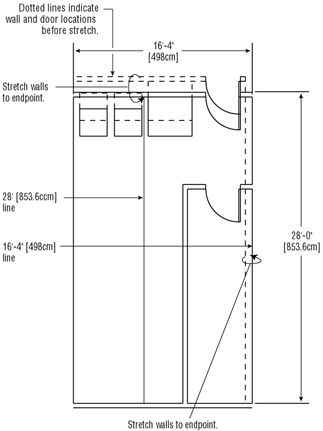
Figure 11.10: The walls stretched to the proper dimensions -
Use the two lines you drew in step 1 to adjust the walls to their proper positions (see Figure 11.10). You can either use the Grips feature or click Stretch on the Modify toolbar.
-
Choose Draw Block Base or type Base . Then make the upper-left corner of the utility room the base point.
-
To add the storage lockers, begin by drawing one 30 ² 30 ² (76 cm 76 cm for metric users) locker accurately.
-

 Use the Mirror and Array commands to create the other lockers. Both commands are available on the Modify toolbar. (For entering objects repeatedly, this is actually a faster and more accurate method than tracing. If you traced each locker, you would also have to clean up each one.)
Finally, you might want to add the dimensions and labels shown earlier in Figure 11.2:
-
Create a layer called Notes to contain the dimensions and labels.
-
Set the Dimscale dimension setting to 48 ( 50 for metric users) before you start dimensioning. To do this, choose Dimension Style from the Dimension toolbar. Make sure the Standard dimension style is selected; then click Modify. In the Modify Dimension Style dialog box, click the Fit tab and click the Use Overall Scale Of radio button. Next, enter 48 ( 50 for metric users) in the input box to the right of the Use Overall Scale Of radio button. (See Chapter 9 for details on this process.)
Tip You can also set the Dimscale setting by typing Dimscale
and then entering the desired scale of 48 . -
Click the Text tab and set the text height to 1 / 8 ² (0.3 for metric users).
-
When you are finished, click OK. Then click Close, save the file, and exit AutoCAD.
Tip Make sure that the text style you are using with your dimension style is set to a height of 0 if you want the dimension style text height to take effect.
Working Smarter with Digitizers
Earlier in this chapter, you traced most of a drawing and used Mirror and Array to speed up the drawing re-creation. However, you could have just traced the major lines with the Ortho mode on, and then used the Offset command to draw the wall thickness. The Fillet and Trim commands (see Chapter 5) could then be used to clean up the drawing where lines cross or where they don't meet.
If you are a civil engineer, you would probably take a different approach. In laying out a road, for instance, you might first trace the center lines and then use the Offset option on the Modify toolbar to place the curb and gutter . You could trace curved features by using arcs (just to see what the radius of the curve is) and then redraw the arc accurately, joining straight-line segments. The digitizer can be a great tool if it is used with care and a touch of creativity.
| |
No discussion of drawing input can be complete without mentioning scanners . Imagine how easy it would be to convert an existing library of drawings into AutoCAD drawing files by simply running them through a scanning device. Unfortunately, scanning drawings is not quite that simple.
In scanning, the drawing size can be a problem. Small-format scanners are cheap and nearly as common as printers. If you need to scan only letters , desktop "all-in-one"scanner/printers in the 8 ½ ² 12 ² (or 26 cm 30 cm) sheet size can be purchased for around $100. Larger scanners up to 12 ² 17 ² can be found in the $1,000 range. But the price of larger scanners in the 24 ² range, the size needed for a typical architectural or engineering drawing, starts to climb dramatically.
After the drawing is scanned and saved as a file, you have two paths to importing it into AutoCAD. One path is to convert the scanned image into AutoCAD objects such as lines, arcs, and circles. This requires special software and is usually a fairly time-consuming process. Finally, the drawing typically requires some cleanup, which can take even longer than cleaning up a traced drawing. The poorer the condition of the original drawing, the more cleanup you'll have to do.
Another path is to import a scanned image directly into AutoCAD and then use all or part of the scanned image in combination with AutoCAD objects. You can use standard AutoCAD tools to trace over the scanned image and then discard the image when you are finished, or you can use the scanned image as part of your AutoCAD file. With AutoCAD's ability to import raster images, you can, for example, import a scanned image of an existing paper drawing and then mask off the area you want to edit. You can then draw over the masked portions to make the required changes.
Whether a scanner can help you depends on your application. If you have drawings that would be difficult to trace ”large, complex topographical maps, for example ”a scanner might well be worth a look. You don't necessarily have to buy one; some scanning services offer excellent value. And if you can accept the quality of a scanned drawing before it is cleaned up, you can save a lot of time. On the other hand, a drawing composed mostly of orthogonal lines and notes might be more easily traced by hand with a large tablet or entered directly by using the drawing's dimensions.
Scanning can be an excellent document management tool for your existing paper drawings. You might consider scanning your existing paper drawings for archiving purposes. Some blueprint companies even offer free large document scanning as an incentive to other digital reproduction services.
You can then use portions or all of your scanned drawings later, without committing to a full-scale, paper- to-AutoCAD scan conversion.
| |
EAN: 2147483647
Pages: 261