Creating Attributes
Attributes depend on blocks. You might think of an attribute as a text information attached to a block. The information can be a description of the block or some other text that may be pertinent. For example, you could include an attribute definition with the door block you created in Chapter 3. Then, every time you subsequently insert the door block, you would be prompted for a value associated with that door. The value can be a number, a height or width value, a name , or any type of text information you want. When you insert the door block, you are prompted for an attribute value. After you enter a value, it is stored as part of the door block within the drawing database. This value can be displayed as text attached to the door block, or it can be invisible. You can change the value at any time. You can even specify the actual prompts for the attribute value.
However, suppose you don't have the attribute information when you design the door block. As an alternative, you can add the attribute to a symbol that is later placed by the door when you know enough about the design to specify what type of door goes where. The standard door type symbol suits this purpose nicely because it is an object that you can set up and use as a block independent of the actual door block.
| Tip | A door type symbol is a graphic code that indicates special characteristics of the associated door. The code refers to a note on another drawing or in a set of written specifications. |
Adding Attributes to Blocks
In the following exercise, you will create a door type symbol, which is commonly used to describe the size , thickness , and other characteristics of any given door in an architectural drawing. The symbol is usually a circle, a hexagon, or a diamond with a number in it. The number is usually cross-referenced to a schedule that lists all the door types and their characteristics.
In this exercise, you will create a new file containing attribute definitions. You could also include such definitions in blocks that you create by using the Make Block tool (the Block command) or in files that you create by using the Wblock command. Just create the attribute definitions as shown here, and then include them with the Block or Wblock selections.
Here are the steps for creating the attribute definition:
-
Create a new file and call it S-door (for symbol-door ). The symbol will fit in the default limits of the drawing, so you don't have to change the limits setting.
-
Draw a circle with a radius of 0.125 ( 0.3 for metric users) and with its center at coordinate 7,5 .
Tip Because this is a new drawing, the circle is automatically placed on Layer0. Remember that objects in a block that are on Layer0 take on the color and line-type assignment of the layer on which the block is inserted.
-
Next , zoom in to the circle so it is about the same size as that shown in Figure 10.1.
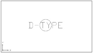
Figure 10.1: The attribute inserted in the circle -
If the circle looks like an octagon, choose View Regen or type Re
 to regenerate your drawing.
 -
Choose Draw Block Define Attributes or type Att
to open the Attribute Definition dialog box. 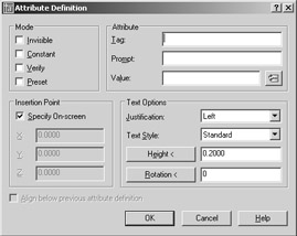
-
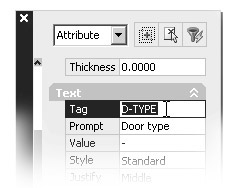
In the Attribute group , click the Tag input box and enter d-type .
Tip The attribute tag is equivalent to a field name in a database. Or you can think of the tag as the name or ID of the attribute. It can help to identify the purpose of the attbibute. The tag can be a maximum of 31 characters but cannot contain spaces. If you plan to use the attribute data in a database program, check that program's documentation for other restrictions on field names .
-
Press the Tab key or click the Prompt input box, and enter Door type . This is the text for the prompt that will appear when you insert the block containing this attribute. Often the prompt is the same as the tag, but it can be anything you like. Unlike the tag, the prompt can include spaces and other special characters.
Tip Use a prompt that gives explicit instructions so the user will know exactly what is expected. Consider including an example within the prompt. (Enclose the example in square brackets to imitate the way AutoCAD prompts often display defaults.)
-
Click the Value input box and enter a hyphen. This is the default value for the door type prompt.
Tip If an attribute is to contain a number that will later be used for sorting in a database, use a default value such as 000 to indicate the number of digits required. The zeros can also serve to remind the user that values less than 100 must be preceded by a leading zero, as in 099.
-
Click the Justification drop-down list and select Middle. This enables you to center the attribute on the circle's center. You might notice several other options in the Text Options group. Because attributes appear as text, you can apply the same settings to them as you would to single- line text.
-
In the input box next to the Height < button, change the value to 0.125. (Metric users should enter 0.3 .) This makes the attribute text 0.125 ² (0.3 cm) high.
-
In the Insertion Point group, select the Specify On-Screen check box.
-
Click OK to close the dialog box.
-
Using the Center Osnap, pick the center of the circle. You need to place the cursor on the circle's circumference, not in the circle's center, to obtain the center by using the Osnap. The attribute definition appears at the center of the circle (see Figure 10.1).
You have just created your first attribute definition. The attribute definition displays its tag in all uppercase letters to help you identify it. When you later insert this file into another drawing, the tag turns into the value you assign to it when it is inserted. If you want only one attribute, you can stop here and save the file. The next section shows how you can quickly add several more attributes to your drawing.
Adding Attribute Specifications
Next, you will add a few more attribute definitions, but instead of using the Attribute Definition dialog box, you will make an arrayed copy of the first attribute and then edit the attribute definition copies. This method can save you time when you want to create several attribute definitions that have similar characteristics. By making copies and editing them, you'll also get a chance to see firsthand how to change an attribute definition.
Follow these steps to make copies of the attribute:
-
Click Array on the Modify toolbar or type Ar
to open the Array dialog box. -
 Click the Rectangular Array radio button in the upper-left corner.
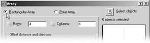
-
 Click the Select Objects button and select the attribute definition you just created. Press to confirm your selection.
 -
In the Rows input box, enter 7 and in the Columns input box, enter 1 .
-
Enter “0.18 in the Row Offset input box ( “0.432 for metric users) and in the Column Offset input box. The Row Offset value is approximately 1.5 times the height of the attribute text height. The minus sign in the Row Offset value causes the array to be drawn downward.
-
Click the OK button.
-
 Issue a Zoom Extents command or click the Zoom Realtime tool to view all the attributes.
Now you are ready to modify the copies of the attribute definitions:
-
Press the Esc key to clear any selections or commands, and click the attribute definition just below the original.
-
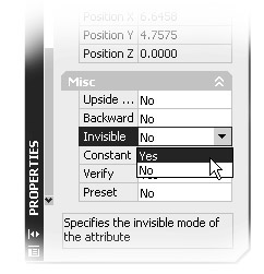
Right-click and choose Properties from the shortcut menu to open the Properties palette.
Tip You can double-click an attribute definition to change its Tag, Prompt, or Default value in the Edit Attribute Definition dialog box. However, this dialog box doesn't let you change an attribute definition's visibility mode.
-
Scroll down the list of properties until you see the Invisible option in the Misc category.
-
Select Yes from the Invisible option drop-down list.
-
Scroll back up the list of properties and locate the Tag option in the Text category.
-
Highlight the Tag value to the right and type D-SIZE
. The attribute changes to reflect the change in the tag value. -
While still in the Text category, highlight the Prompt value and type Door size
. -
In the Value field, type 3 ¢ -0 ²
. Metric users should type 90 . Tip Make sure you press
after entering a new value for the properties in the Properties palette. Pressing confirms your new entry.
You've just learned how to edit an attribute definition. Now you'll make changes to the other attribute definitions:
-
Press the Esc key so that no attribute is selected, and then click the next attribute down so you can display its properties in the Properties palette.
-
Continue to edit this and the rest of the attribute definition properties by using the attribute settings listed in Table 10.1.To do this, repeat steps 4 through 8 of the preceding exercise for each attribute definition, replacing the Tag, Prompt, and Default Values with those shown in Table 10.1. Also, make sure all but the original attributes have the Invisible option selected.
-
When you've finished editing the attribute definition properties, close the Properties palette.
-
Choose Draw Block Base to change the base point of this drawing to the center of the circle. Use the Center Osnap to get the exact center.
-
Now you have finished creating your door type symbol with attributes. Save the S-door file.
When you later insert a file or a block containing attributes, the attribute prompts will appear in the order that their associated definitions were created. If the order of the prompts at insertion time is important, you can control it by editing the attribute definitions so their creation order corresponds to the desired prompt order. You can also control the order by using the Block Attribute Manager, which you'll look at later in this chapter.
| Tag | Prompt | Default Value |
|---|---|---|
| D-NUMBER | Door number | - |
| D-THICK | Door thickness | - |
| D-RATE | Fire rating | - |
| D-MATRL | Door material | - |
| D-CONST | Door construction | - |
| Make sure the Invisible option is selected. | ||
| |
In the Attribute Definition dialog box, you saw several choices in the Mode group, and you've used two of these modes to see what they do. You won't use any of the other modes in this tutorial, so here is a list describing all the modes for your reference:.
Invisible Controls whether the attribute is shown as part of the drawing.
Constant Creates an attribute that does not prompt you to enter a value. Instead, the attribute simply has a constant, or fixed, value you give it during creation. The Constant mode is used when you know you will assign a fixed value to an object. After constant values are set in a block, you cannot change them by using the standard set of attribute-editing commands.
Verify Causes AutoCAD to review the attribute values you enter at insertion time and to ask you whether they are correct. This option only appears when the attribute dialog box is turned off (the Attdia system variable is set to 0).
Preset Causes AutoCAD to automatically assign the default value to an attribute when its block is inserted. This saves time because a preset attribute will not prompt you for a value. Unlike the Constant mode, a Preset attribute can be edited.
You can have all four modes on, all four off, or any combination of on and off. With the exception of the Invisible mode, none of these modes can be altered after the attribute becomes part of a block. Later in this chapter, I'll show you how to make an invisible attribute visible.
| |
Inserting Blocks Containing Attributes
In the preceding section, you created a door type symbol at the desired size for the actual plotted symbol. This means that whenever you insert that symbol, you have to specify an X and Y scale factor appropriate to the scale of your drawing. This enables you to use the same symbol in any drawing, regardless of its scale. (You could have several door type symbols, one for each scale you anticipate using, but this would be inefficient.)
The following steps demonstrate the process of inserting a block that contains attributes:
-
On the CD Open the Plan file you created in earlier exercises. Or you can use the 10a-plan.dwg file from the companion CD. Metric users can use the file named 06b-plan-metric.dwg (from the CD's Chapter 6 folder).
-
Turn on the Attribute Dialog mode by entering Attdia
1 at the command prompt. This enables you to enter attribute values through a dialog box in the next exercise. -
Choose View Named Views to restore the view named First.
-
Be sure the Ceiling and Flr-pat layers are off. Normally in a floor plan, the door headers are not visible, and they will interfere with the placement of the door reference symbol.
-
Click the Insert Block tool or type I
to open the Insert dialog box. -
Click the Browse button.
-
Locate the S-door file in the file list and double-click it.
-
In the Insertion Point group, make sure that the Specify On-screen option is turned on.
-
In the Scale group, make sure the Uniform Scale check box is selected; then enter 96 in the X input box. Metric users should enter 100 in the X input box.
-
In the Rotation group, make sure that the Specify ON-screen option is turned off; then Click OK.
You created the S-door file at the actual plotted size, so in step 9, you needed to scale it up by the drawing scale factor to make it the appropriate size for this drawing.
Now you're ready to place the file in your drawing and enter the attribute values for the symbol:
-
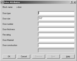
AutoCAD is waiting for you to select a location for the symbol. To place the symbol, click in the doorway of the lower-left unit, near coordinate 41 ¢ -3 ² ,72 ¢ -4 ² . Metric users should use coordinate 1256,2202. When you click the location, the Enter Attributes dialog box opens.
-
In the Door Type input box, enter A
. Note that this prompt is the prompt you created. Note also that the default value is the hyphen you specified. Tip Attribute data is case sensitive, so any text you enter in all capital letters will be stored in all capital letters.
-
In the Door Number input box, change the hyphen to 116 . Continue to change the values for each input box, as shown in Table 10.2.
-
When you are finished changing values, click OK, and the symbol appears. The only attribute you can see is the one you selected to be visible: the door type.
Tip If the symbol does not appear, go back to the S-door.dwg file and make sure you have set the base point to the center of the circle.
Table 10.2: Attribute Values for the Typical Studio Entry Door Prompt
Value
Door type
A
Door number
(Will be same as room number)
Door thickness
1 ¾ ²
Fire rating
20 min.
Door material
Wood
Door construction
Solid core
-
Add the rest of the door type symbols for the apartment entry doors by copying or arraying the door symbol you just inserted. You can use the previously saved views to help you get around the drawing quickly. Don't worry that the attribute values won't be appropriate for each unit. You'll see how to edit the attributes in the next section.
As a review exercise, you'll now create another file for the apartment number symbol (shown in Figure 10.2). This will be a rectangular box with the room number that you will place in each studio apartment. Follow these steps:
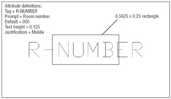
Figure 10.2: The apartment number symbol
-
Save the Plan file and then open a new file called S-apart (for the apartment number symbol).
-
Create an attribute definition and give it the tag name R-NUMBER , the prompt Room number , a default value of 000 , and a text height of 0.125 ² .
-
Use the Base command (choose Draw Block Base) to set the base point of this drawing in the lower-left corner of the rectangle.
-
Save and close S-apart .
-
Open the Plan file again and insert the S-apart drawing you just created (using an X scale factor of 96) into the lower-left unit. Give this attribute the value 116 .
-
Copy or array the room number symbol so that there is one symbol in each of the units. You'll learn how to modify the attributes to reflect their proper values in the following section, "Editing Attributes." Figure 10.3 shows what the view should look like after you've entered the door symbols and the apartment numbers .
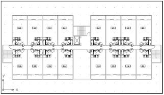
Figure 10.3: An overall view of the plan with door symbols and apartment numbers added
EAN: 2147483647
Pages: 261