HP ProLiant Essentials Workload Management Pack
| < Day Day Up > |
| WMP provides the tools you need to consolidate applications and take advantage of any underutilized server assets. Resource Partitioning Manager (RPM), the featured software within WMP, is a software solution that controls and dynamically allocates system resources to enable application consolidation and performance optimization on Windows server platforms. WMP enables maximizing server utilization for lower Total Cost of Ownership (TCO) and improved availability. This section provides information on how to use RPM to create resource partitions, limit each partition to specific resource quantities , and establish rules that allow for the dynamic reallocation of processors and memory. It also explains new features for v2.0, such as system overview charts , event logging, data trending, and process metering and reporting. WMP Product FeaturesWMP offers users a variety of powerful features. Some of the more popular ones are listed here:
RPM's Partition Configuration Wizard quickly groups processes, allocates resources, and assigns applications to resource partitions to simplify setup. RPM utilizes OS-native Microsoft job objects to create resource partitions that contain processes within a CPU and memory context; the partition eliminates system crashes due to runaway processes and memory leaks enabling application stacking and server consolidation. RPM also includes a Dynamic Rules Engine that dynamically scales resource partitions up or down based on schedule, events, or demand. These rules provide flexibility to automatically add or remove resources without user intervention. The easy-to-use GUI minimizes the time needed to train Administrators and staff on how to manage workloads and configure the server. RPM's easy-to-follow graphing capabilities provide
WMP also understands Hyper Threading Technology (virtual processors) is appropriate for one to eight processor systems and beyond, and is licensed per system not per CPU. In addition to creating resource partitions, RPM enables you to do the following:
Microsoft Windows System Resource Manager (WSRM)Windows Server 2003 Enterprise and Datacenter Editions have a tool similar in functionality to WMP, called the Windows System Resource Manager (WSRM). However, whereas WSRM is not integrated with the OS and is only licensed with Windows Server 2003 Enterprise and Datacenter Editions, WMP can be used with all versions of Windows 2000 and Windows Server 2003, including Web Edition (and even Windows XP). In addition, customers can use WMP on Windows 2000 without migrating to Windows Server 2003; as migration begins, they can continue to use the same tool. Besides being less expensive than WSRM, WMP has an easier-to-use interface, covers more application scenarios, and contains a sophisticated rules engine that WSRM lacks. What's New in WMP v2.0?The WMP features RPM v2.0 and contains all the functionality offered in v1.1 of RPM. In addition, it offers the following features, which provide more automation, more performance and utilization data, and greater configuration flexibility:
Typical Uses for WMPYou can use WMP for a variety of applications. Some of the more typical uses are listed here:
HP Resource Partition ManagerHP RPM, the featured software within the WMP, is a software solution that controls and dynamically allocates system resources to enable application consolidation and performance optimization on Windows server platforms. A resource partition is a defined set of processor and memory resources assigned to a Windows job object. A job object is a feature of Windows 2003 and 2000 that allows a user to group processes together. These job objects can be thought of as containers that hold user-defined applications, services, and other processes. RPM creates and manages resource partitions whose boundaries can be dynamically reallocated based on the resource needs of the objects. Some applications can create job objects outside of RPM. This book refers to this type of job object as a non- RPM job object . To ensure that the allocation of all system resources is monitored , RPM has the capability to "capture" these non-RPM job objects in a resource partition using the Capture function under the Partition option on the RPM menu bar. Installing RPMBefore installing RPM, make sure your system meets the following necessary requirements:
Also, note that HP lists the following restrictions and recommendations when running RPM:
tip Refer to the troubleshooting section of the RPM User Guide v2.0 for more information about running multiple instances of the same application. Installation InstructionsUse the following instructions to install RPM on the ProLiant server:
After installation is complete, a shortcut to RPM is added to the desktop. note A system reboot is not required following the installation of RPM. Upgrade InstructionsUse the following instructions to upgrade from an earlier version of RPM:
The upgrade process shuts down the RPM service if it's active, and then overwrites it with the new version of the software. After installation is complete, a shortcut to RPM 2.0 is added to the desktop. note Partitions created in an older version of RPM remain intact after an upgrade. Also, a system reboot is not required following an upgrade of RPM. Using RPMWhen RPM is launched, the user interface (UI) is displayed. The UI serves as the control point for all RPM functions. However, because RPM controls resources using the RPM service, the UI does not need to be active at all times. The UI window can be closed at any time without affecting the configurations, rules, or execution of any resource partition. When you have finished creating and activating resource partitions, you can keep RPM visible, minimize RPM, or close the UI window completely and move on to other activities while RPM manages your resources in the background. The main screen of the UI, shown in Figure 8.4, is used to create, edit, activate, deactivate, or delete resource partitions. The graphics displayed on the main screen can be used to view existing resource partitions, as well as processor and memory details for the server. The main screen consists of four elements: a menu bar, a toolbar, resource partition panels, and processor and memory graphs. Figure 8.4. RPM main UI.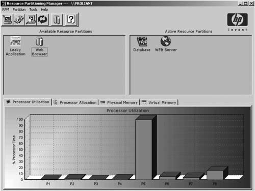 The RPM menu bar contains the following menus :
Table 8.1 describes the icons and functions of the RPM toolbar found at the top of the main screen. Table 8.1. RPM Main Screen toolbar
The main window of the UI includes the Available Resource Partitions panel and the Active Resource Partitions panel. The Available Resource Partitions panel, shown in Figure 8.5, contains inactive resource partitions that have been previously defined. Figure 8.5. Available resource partitions. The Active Resource Partitions panel, shown in Figure 8.6, contains all resource partitions currently active on the server. Figure 8.6. Active resource partitions. The bottom section of the main window displays processor and memory utilization and allocation graphs. The Processor Utilization tab, shown in Figure 8.7, displays the current processor utilization for all system activity. Figure 8.7. The Processor Utilization tab.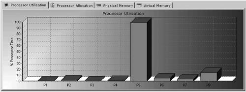 The Processor Allocation tab, shown in Figure 8.8, displays which processors are assigned to which partitions. Figure 8.8. The Processor Allocation tab. The Physical Memory tab, shown in Figure 8.9, displays the current amount of physical memory in use by each active resource partition. Figure 8.9. The Physical Memory tab. The Virtual Memory tab, shown in Figure 8.10, displays the amount of virtual memory in use for each active resource partition. Figure 8.10. The Virtual Memory tab. Using Resource PartitionsThe core purpose of the RPM is to contain processes within defined resource partitions and to have those processes obey the configured boundaries of their associated partitions. These boundaries are defined during the process of creating a resource partition. Creating a Resource PartitionThis section explains how to create a resource partition on a local system. For instructions on creating a resource partition on a remote system, refer to the "Using Resource Partitioning Manager on a Target Machine" section of the RPM User Guide v2.0. Following is an overview of the three steps required to create a resource partition on a local system:
note For in-depth details and descriptions for these processes, see the RPM User Guide v2.0. The first step in creating a resource partition is to set the basic properties for the partition. Click the Create Resource Partition icon on the toolbar or select Partition, Create from the main menu to launch the Resource Partition Creation Wizard. The Resource Partition Properties dialog box is displayed (see Figure 8.11). Figure 8.11. The Resource Partition Properties dialog box. The Resource Partition Properties dialog box allows you to name a partition, assign an owner to the partition, define the basic processor and memory resources available to the partition, and assign other partition attributes to the target system. To create a resource partition, follow these steps:
note For information about how associated processes can be started when the resource partition is activated, refer to the "Adding an Active Process Using the Capture Method" section in the RPM User Guide v2.0. To set the amount of total virtual memory available to a partition, enter the desired maximum value (in megabytes) in the Maximum Size (MB) text box. A partition must be allocated a minimum of 16MB of virtual memory, with the maximum possible value determined by the machine configuration (and displayed next to the Virtual Memory Maximum label). The Processors Tab and the Virtual Memory TabAs you saw previously in Figure 8.11, the lower part of the Resource Partitions Properties dialog box contains a Processors tab and a Virtual Memory tab. The Processors tab graphs the number of resource partitions that are allocated to each processor. The Virtual Memory tab graphs the maximum virtual memory for each resource partition. The allocation bars on both tabs are color -coded by resource partition. note A single processor can be assigned to multiple resource partitions; however, this can impact performance. The Display Active Partitions button controls the display of the processor allocation chart. If you click the Display Active Partitions button, the chart shows only objects that are currently active, and the text on the button changes to Display All Partitions. If you click the Display All Partitions button, all objects (both active and inactive) are displayed. Advanced FeaturesRPM offers several advanced features. To modify these advanced features, click the Advanced tab in the Resource Partitions Properties dialog box, as shown in Figure 8.12. Figure 8.12. The Advanced tab in the Resource Partition Properties dialog box. warning You should fully understand the implications of each of the settings on the Advanced tab before using them. If you are unfamiliar with the significance of Advanced tab settings within the Windows OS, you should avoid their use. Here is a list of the features you'll find on the Advanced tab settings, along with a description of what these features do:
note By default, each user process on the 32-bit version of Windows 2000/2003 can have up to a 4GB private address space, where 2GB are allocated to the private address, and the remaining 2GB are used by the OS. Windows 2000/2003 Advanced Server and Windows 2000/2003 Datacenter Server support a boot-time option that allows 3GB user address spaces. RPM automatically recognizes that the system is running in this configuration and adjusts the value for Virtual Memory Maximum accordingly . The Resource Partition Processes Dialog BoxAfter you finish reviewing the settings for Resource Partition Properties, click Next. The Resource Partition Processes dialog box is displayed (see Figure 8.13). The Resource Partition Processes dialog box is the starting point for adding any process to a resource partition. Figure 8.13. The Resource Partition Processes dialog box.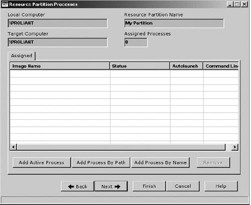 There are three methods for adding a process into a resource partition: Add Active Process, Add Process by Path , and Add Process by Name. The Add Active Process method captures the process information from a running process by selecting it from a Task Manager style list. This method provides a simple way to add a running process to the resource partition. To use this method, from the Resource Partition Processes dialog box (refer to Figure 8.13) click the Add Active Process button. The Add Active Process dialog box is displayed (see Figure 8.14). Figure 8.14. The Add Active Process dialog box. This screen displays two list boxes. The left list box shows all processes running on the system, with the exception of certain system and kernel processes that are excluded to avoid potential conflict issues. To capture a process within the resource partition, double-click the target image name in the left list box to move it to the Processes To Be Assigned list on the right, or highlight the target image name and click Add. warning Adding a running process to a resource partition causes that process to be terminated if the partition is later deactivated. The Add Process by Path method indicates the exact file path (on your hard drive, for example) of an executable representing the process. With this method, a new process can be added to the resource partition by pointing to the location of the executable file that is associated with the process. To use this method from the Resource Partition Processes dialog box, click Add Process By Path. When the Add Process By Path dialog box is displayed (see Figure 8.15), enter the path directly or click the Browse button to browse to the target executable file. Figure 8.15. The Add Process By Path dialog box. For processes specified using this method, two additional options are available under the Advanced button, as shown in Figure 8.16:
Figure 8.16. The Advanced Process Properties dialog box. After you specify the path name, click Finish to save the changes. The newly added process will appear in the Assigned processes list on the Resource Partition Processes dialog box. note RPM can be used to specify processes for executables accessed over a network. However, these executables must be accessible by means of a previously configured network share drive. The third method by which you can add a process into a resource partition, the Add Process by Name method, indicates the image name that the process will run under when executed. The image name of a process can be viewed under Task Manager when that process is active. This method is useful where multiple instances of a specific application are running on the same system and might not be identifiable by the executable path. This method allows you to indicate an image name for a specific instance of an application. To begin this method, click Add Process By Name on the Resource Partition Processes dialog box. When the Add Process By Name dialog box is displayed (see Figure 8.17), enter the exact image name that the process runs under and click Finish. Figure 8.17. The Add Process By Name dialog box. After creating the partitions, you can view the processes assigned to each partition through the Resource Partition Processes dialog box. Two different process views are available: Assigned and Active. Available resource partitions contain assigned processes. Active resource partitions show both assigned and active processes. To view a list of processes that have been assigned to a resource partition, click the Assigned tab. Figure 8.18 shows an example of this view, which is the default view for the Resource Partition Processes dialog box. Figure 8.18. The Assigned tab of the Resource Partition Processes dialog box.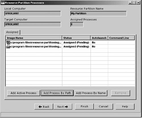 The following information is provided about each assigned process:
The Active tab displays those processes that are running within the resource partition when it is active, including those processes that are called from the assigned process. Figure 8.19 shows an example of this view. Figure 8.19. The Active tab of the Resource Partition Processes dialog box.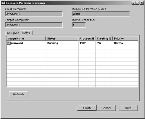 The following information is provided about each process:
Click the Refresh button to update the information in the process list. To add more processes, repeat the steps for the desired method. Processes will be shown on the Assigned tab of the Resource Partition Processes dialog box as they are added to the resource partition. To remove a process from a partition, select the process image name in the list view under the Assigned tab and click Remove. You can remove processes from both available and active resource partitions. After all desired processes are assigned to the partition, click Next to set the rules for the newly created resource partition, or click Finish to save the resource partition and return to the main screen. Resource Partition RulesAfter a process has been assigned to a resource partition, rules can be associated with that resource partition, enabling RPM to dynamically reallocate processors and memory. The Resource Partition Rules dialog box enables you to modify these four types of rules:
Processor and memory rules dynamically adjust the resource allocations of a partition from the initial settings defined on the Resource Partitions Properties dialog box in order to optimize system performance. When a resource partition is activated for the first time, the initially allocated processors and memory are used. Thereafter, the rules take precedence over the initial settings. note For information about modifying Resource Partition Rules, refer to the "Resource Partition Rules" section in the RPM User Guide v2.0. Capturing a Non-RPM Job ObjectSome applications can create job objects outside of RPM. To ensure that the allocation of all system resources is monitored, RPM has the ability to capture these non-RPM job objects in a resource partition. warning RPM utilizes the Job Object Application Program Interface (API) available in Windows 2000 and Windows Server 2003. In some cases, other applications may also create job objects using this technology. Job objects created by either the OS or applications other than RPM should not be captured by RPM unless a specific need to do so has been identified. Capturing those objects and modifying their properties could create conflict between RPM and the originating application To capture a non-RPM job object, follow these steps:
note Unlike regular resource partitions, moving a partition created from a non-RPM job object from the panel to the Available Resource Partitions panel does not terminate the processes in the partition. The System and Resource Partition Overview Dialog BoxesThe System and Resource Partition Overview dialog boxes provide two different ways to view and evaluate real-time performance on an RPM-managed server:
Using the System Overview ChartsTo use the System Overview, select RPM, System Overview from the menu bar, or click the System Overview icon on the toolbar. You will see several tabs, as described in the following sections. The Overview TabThe System Overview opens with the Overview tab, as shown in Figure 8.21. The Overview tab provides selected performance information for the following:
Figure 8.21. The Overview tab. The Processor TabThe Processor tab, shown in Figure 8.22, displays information about all processors recognized by Windows 2000/2003 OSs. The remainder of this section provides detailed information about each processor chart. Figure 8.22. The Processor tab. note Processor numbering is consistent with Windows 2000/2003 Server processor numbering. The Processor Utilization screen provides a measurement of how busy the processor is executing requests. Each request takes up a portion of the work capability of the processor. As more and more requests are made to the processor, the processor can become overburdened with requests, resulting in high processor utilization and slower response times. When the processor does not have requests to complete, an idle process is executed. A high processor utilization percentile means that the processor is always busy responding to requests, so the idle process is never executed. The overall processor utilization totals are divided into Kernal Mode and User Mode:
This information helps you to discern between the application workload and the system processes workload. The Processor Balance screen displays processor utilization data per processor. The location of the processor icon around the ring indicates the percentage of utilization for that processor. The Processor Utilization screen shows the Total Processor Time versus deferred procedure calls deferred procedure calls (DPCs) Queued per Second, which is a current measurement of the outstanding DPCs. When a hardware device interrupts the processor, the Interrupt Handler may elect to execute the majority of its work in a DPC. DPCs run at lower priority than interrupts, and therefore permit interrupts to occur while DPCs are being executed. The Total Processor Utilization screen displays an overall average of all processor utilization rates. This information gives a good indication of overall processor loading over a period of time. The Memory TabThe Memory tab, shown in Figure 8.23, displays information about all memory installed in the system and recognized by Windows 2000/2003 Server OSs. The rest of this section provides detailed information about each memory chart. Figure 8.23. The Memory tab. The Physical Memory Utilization screen displays the percentage of memory currently being used by the system. The percentage of memory in use is the ratio of available memory to total physical memory. The Physical Memory Utilization screen displays these utilization statistics:
As more and more memory is being used by the system, less memory is available for other applications or to buffer disk requests. A low amount of available memory can impact system performance. The Resident System Cache screen displays the number of bytes allocated for the file system cache resident in the physical memory. This value includes only current physical pages and does not include any virtual memory pages not currently resident in the physical memory. The system cache is a temporary location for data that is otherwise resident in disk storage. Because accessing data in cache is significantly faster than accessing disk data, it is an advantage to have sufficient cache storage. The Memory Page Faults screen displays the overall rate at which faulted pages are handled by the processor. Numerous page faults can be an indication that more memory is needed to sustain optimum performance. The Memory Paging Activity screen displays pages input/pages output per second:
Windows 2000/2003 Server writes pages to disk to free up space when physical memory is in short supply. A high rate of paging (pages in or pages out) might indicate a memory shortage. The Physical Disk TabThe Physical Disk tab displays information about all physical disks attached to the system and recognized by Windows 2000/2003 Server OSs (see Figure 8.24). The remainder of this section provides detailed information about each physical disk chart. Figure 8.24. The Physical Disk tab. The Current Disk Utilization screen displays the percentage of time the disk is servicing read and/or write requests. This chart indicates how busy the disk is. Low processor utilization and high disk utilization could indicate a disk performance limitation. The Average Disk Queue Length screen displays the length of outstanding read/write requests queued for the disk. This screen measures the length of time the controller takes to complete outstanding requests. A performance limitation might occur if the disk controller is not able to keep up with the number of requests being received. The Average Disk Latency screen displays the time in milliseconds of the average disk transfer. When a request is received, a timer starts. When the request is completed, the timer stops, providing a measure of the time for disk transfer. This chart can indicate how well the disk is responding to transfers. The Disk Transfer Rate screen displays the rate at which bytes are transferred to or from the disk during write/read operations. This chart measures data transfer rates over a period of time. Data transfer rates indicate how much work the controller is performing. The Network TabThe Network tab displays information about all network interfaces attached to the system and recognized by Windows 2000/2003 Server OSs (see Figure 8.25). The remainder of this section provides detailed information about each network chart. Figure 8.25. The Network tab. The Network Traffic (KB/Sec) screen displays the rate at which bytes of data are sent over the network. Over a period of time, this screen updates to indicate how many bytes have been transferred. A consistently high rate of network traffic could indicate performance limitations. The Network Output Queue Length screen displays the number of packets in the output queue. This chart indicates the number of outstanding packets. An elevated queue length over an extended period of time could indicate a network performance problem. The Network Traffic (Packets/Sec) screen displays the rate at which packets are sent over the interface. A consistently high rate of packets per second could indicate performance limitations. The Network Maximum Configured Link Speed screen displays the currently configured maximum rate of the network interface. This data can be used to verify proper configuration of installed NICs. note The Network Maximum Configured Link Speed graph indicates system potential and can be expected to remain static. Using the Resource Partition Overview ChartsThe Resource Partition Overview charts provide a real-time view of resource utilization at the resource partition level. Processor, memory, and disk and network I/O charts reflect how the applications and processes contained in a resource partition are utilizing the resources available to them. To use the Resource Partition Overview, follow these steps :
Refer to the following sections for explanations of each tab and its contents. The Processor TabThe Processor tab displays information about the processors used by the resource partition (see Figure 8.26). The remainder of this section provides detailed information about each processor chart. Figure 8.26. The Processor tab. note Processor numbering is consistent with Windows 2000/2003 Server processor numbering. The Processor Utilization screen provides a measurement of how busy the processor is executing requests. Each request takes up a portion of the work capability of the processor. As more and more requests are made to the processor, the processor can become overburdened, resulting in high processor utilization and slower response times. When the processor does not have requests to complete, an idle process is executed. A high processor utilization percentile means that the processor is always busy responding to requests, so the idle process is never executed. The overall processor utilization totals are divided into Kernel Mode and User Mode:
The Total Processor Utilization screen displays the percentage of total available processor time used by this resource partition. This information gives a good indication of overall processor loading over a period of time. The Partition Processor Time screen displays a running sampling of the raw amount of processor time utilized by the partition. This information provides a good indication of processor activity for the partition over time. The Active Processes screen displays how many processes are currently active on the resource partition. The Memory TabThe Memory tab displays information about the memory used by the partition (see Figure 8.27). The remainder of this section provides detailed information about each memory chart. Figure 8.27. The Memory tab. The Physical Memory Utilization screen displays the percentage of memory currently being used by the resource partition. The percentage of memory in use is the ratio of utilized memory to total physical memory. As more and more memory is being used by the system, less memory is available for other applications or to buffer disk requests. A high rate of utilization can impact system performance. The Virtual Memory Utilization screen displays the total amount of virtual memory currently being used by all processes within the resource partition. The Memory Page Faults screen displays the overall rate at which faulted pages are handled by the processor. Numerous page faults can be an indication that more memory is needed to sustain optimum performance. The Page File Utilization screen displays the amount of storage this partition is utilizing in the paging files. Paging files are shared by all processes, so lack of space in paging files can prevent other processes from allocating memory. The I/O TabThe I/O tab provides read and write information about network, file, and device I/O operations (see Figure 8.28). The remainder of this section provides detailed information about each I/O chart. Figure 8.28. The I/O tab. The Partition Read Operations screen indicates the rate at which processes in this resource partition are issuing read I/O operations. The Partition Read Rate screen indicates the rate at which processes in this resource partition are reading data from I/O operations. The Partition Write Operations screen indicates the rate at which processes in this resource partition are issuing write I/O operations. The Partition Write Rate screen indicates the rate at which processes in this partition are writing data from I/O operations. Additional ToolsA variety of additional tools provide methods for managing the RPM service, exporting and importing partition files, tracking system and resource partition data, accessing scripting capabilities, creating reports based on collected data, customizing charts, and setting partition defaults. Here is a list of the additional tools:
note For information about additional tools, refer to the "Additional Tools" section in the RPM User Guide v2.0. For additional information on ProLiant Essentials WMP and Exchange Consolidation, Server Consolidation, and best practices see the HP Web site at http://h18000.www1.hp.com/products/servers/proliantessentials/wmpdocumentation.html . |
| < Day Day Up > |
EAN: N/A
Pages: 214
- Challenging the Unpredictable: Changeable Order Management Systems
- ERP System Acquisition: A Process Model and Results From an Austrian Survey
- The Second Wave ERP Market: An Australian Viewpoint
- Data Mining for Business Process Reengineering
- Healthcare Information: From Administrative to Practice Databases