Understanding a Frame Relay Network
Frame relay is the next generation of data transfer solutions, and it was created to replace private line networks that used to crisscross the nation, costing businesses too much money. Sometimes private lines are installed for redundancy, but they are rarely used to their full potential because they exist only as a safety net if another connection fails.
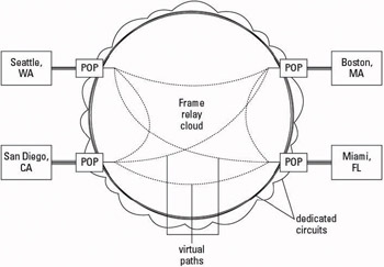
Frame relay takes information from the office, stuffs it in a nice little package, places a destination and return address on it, and sends it on its way along with all the other packages the carrier is processing. Figure 14-3 shows a typical, fully redundant setup for a frame relay network with four nodes (individual locations on the frame relay network).
Tip Frame relay is a logical transition if you currently connect multiple offices with private lines. It is also an option if you’re looking for a more secure way to transmit data to many offices, because frame relay is more secure than the public Internet.
Drawbacks of frame relay networks
One of the drawbacks of frame relay is that you must order dedicated circuits to connect each of your offices to your carrier’s frame relay network. These dedicated circuits are shown as the triple lines in Figure 14-3, connecting each location to a POP; they typically cost between $200 and $800 each for a T-1 connection.
Frame relay technology was a great step forward when compared to private lines. However, the cost of PVCs (permanent virtual circuits), and the limited number of PVCs available, are issues that you can’t ignore. For more information about PVCs (which are represented in Figure 14-3 with dashed lines), check out the following section, “Frame relay element #3: The permanent virtual circuit, or PVC.”

Figure 14-3: A frame relay network with four nodes. The dashed lines are individual permanent virtual circuits (PVCs).
In addition to the PVC problem, frame relay networks are unable to route calls around problem areas or prioritize them. These issues in particular have spawned a new technology called Multi-Protocol Label Switching, or MPLS. MPLS was designed to overcome the limitations of frame relay. For more information about MPLS, see the section, later in this chapter, called “New and Improved Transmission for Multiple Locations.”
The frame relay cloud in the center of Figure 14-3 makes setting up data transfer between four distant locations more cost-effective than the same setup with private lines. As you see, all the lines within the cloud are dashed, indicating that the path your data travels isn’t a dedicated span that only you alone can use, but is instead a virtual path between two points that many customers share.
Frame relay has three main pieces that allow it to work, and each one is generally listed as a separate line item when you receive a quote for the service from your carrier. These three charges apply to every site connected to the frame relay network, and if any are missing when you receive your quote, you should confirm that the locations are available through your carrier.
Tip You need to have some hardware if you’re going to have a frame relay network. The following sections list all the elements you need to order. The elements are available in a variety of sizes to fit your exact requirements.
Frame relay element #1: The local loop
Just like the long-distance circuit needed for voice calls, you have to order a local loop to connect the router at your office to your carrier’s frame relay network. You can order a local loop only in standard dedicated loop increments: 64 kbps, full T-1, or full DS-3. Even if you only need 256 or 512 kbps, you still have to order a full T-1 for your local loop. Your carrier might tell you that it can provide a fractional T-1 (a portion of a full T-1) local loop, but it will still charge you for the full bandwidth.
The cost of the frame relay local loop might be more than a local loop used for a voice circuit, because your carrier has to receive the circuit in at a certain place in the network where the carrier has access to the frame relay network. Not every voice POP your carrier has can access the frame relay network.
Frame relay element #2: The frame relay port
The frame relay port is where your local loop terminates at the entrance portal to your carrier’s frame relay network. The port can vary in size, based on 64 kbps increments (just like the DS-0 channels on a T-1), depending on how much bandwidth you need. This means that you can order a 256 kbps port, but not a 220 kbps port.
Frame relay element #3: The permanent virtual circuit, or PVC
The permanent virtual circuit, or PVC, is the dashed line within the frame relay cloud that allows your data to travel from one frame relay node to another. Your data doesn’t have exclusive rights to the path it takes between the nodes as it does in a private line. Your data is instead packaged into a frame, numbered sequentially based on how it was made, and labeled with a destination address in the header before it’s sent off into the frame cloud. When it’s in the frame relay network, your data is routed along to the required destination at the other end of your PVC.
You can purchase the PVC, just like the port and the local loop, in varying sizes, depending on your requirements. Just like the frame relay port, you can request the PVC in any standard telecom size in increments of 64 kbps (sometimes even in 56 kbps increments).
Technical Stuff PVCs are identified within the frame relay network by data-link connection identifiers (DLCIs), which the frame relay provider assigns to each end of the PVC. These DLCI numbers exist in a limited range from roughly 16 to 991 (the available range of numbers has changed over time) and are only recognized within the frame relay network. This limitation was overcome by an enhancement including Local Management Interface (LMI) functionality, thus allowing additional nodes to be attributed to a single DLCI known within the frame relay network.
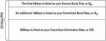
Remember When you order a PVC, you are rarely given all the bandwidth you ordered. When you order a 256 kbps PVC, for example, you might be guaranteed only a portion of that bandwidth. Figure 14-4 gives you a good idea of how a PVC is partitioned:

Figure 14-4: How a typical permanent virtual circuit (PVC) is partitioned.
Understanding your virtual circuit’s bandwidth needs
Your frame relay network’s permanent virtual circuit (PVC) is actually composed of several layers of bandwidth that you don’t have complete and constant access to. The percentages of your total PVC that make up each layer are sometimes set by your carrier, or you might be able to adjust the percentages by paying more money for larger sections of guaranteed bandwidth. The following sections identify your options.
Committed information rate: CIR
The committed information rate, or CIR, is the most important part of your PVC. This is the amount of bandwidth you have guaranteed access to at all times.
Remember CIR sizes vary by carrier. Every carrier has a different policy on how it assigns the CIR for its PVCs. Some carriers give you a CIR that is equal to the size of the PVC you have ordered, and some guarantee you only a quarter of the PVC bandwidth for your CIR. You might be able to pay more for a higher level of CIR, so check with your carrier if necessary. As a standard rule, request at least 50 percent of the total bandwidth of your PVC to be designated as CIR; you don’t want to lose data because you are using too much of your bursting bandwidth.
Committed burst rate: Bc
The committed burst rate is the additional bandwidth your carrier guarantees you can burst to for short duration use. The carrier generally doesn’t tell you how long you can burst and use this bandwidth; it only tells you that it’s for bursting. This bandwidth is used during your peak times when you are sending or receiving large quantities of data, but isn’t the average bandwidth used during normal business hours. This extra burst of bandwidth is for instances such as sending your weekly database file to the accounting office. It isn’t the typical transmission level you work at on a day-to-day basis, but once a week you may need the extra room.
Excess Burst Size: Be
The excess burst size is the additional bandwidth that you can use, as long as nobody else is using it. Imagine that two PVCs built next to each other are five lanes of a highway, with two lanes devoted to traffic in each direction and the shared center lane to be used for passing. The center lane is your Be bandwidth.
Be is room that you can use, as long as nobody (that is, no data) is coming in the opposite direction. The router sending packets into the PVC from your side can monitor traffic it is sending, but can’t anticipate whether another router in the frame relay network is sending any large files back over the PVC. If you have two packets of data come into contact in the Be bandwidth section of the PVC, both frames of data are blown away and sent into the bit bucket. Luckily, the data is automatically sent again, so you don’t really lose that much.
EAN: 2147483647
Pages: 184