Overview of ARCnet
| ARCnet stands for Attached Resource Computer Network. Because it is a token-passing system, ARCnet is a deterministic network technology that is useful in situations where a predictable throughput is required. It was a very popular technology during the early 1980s, when Ethernet was still quite expensive and most local area networks were small. Its speed of 2.5Mbps was more than sufficient for implementing ARCnet in a small office network, given the relative power of PCs and minicomputers at that time. Now, it is most likely to be found in older departmental LANs (though I've never seen one) or in an industrial manufacturing plant or another similar setting. The basic ARCnet operates at a rate of 2.5Mbps and can be used to create a LAN of as many as 255 computers. Some network hardware vendors produce network adapters and hubs that allow for speeds up to 10Mbps. Although ARCnet is no longer marketed primarily as a PC LAN solution, it does have many features that make it well suited for industrial applications. Factory floor automation requires that controllers and other devices have a communications network in place that allows for reliable, predictable throughput. The following are some of the reasons why ARCnet is still in use today, in environments such as this:
In an environment such as factory automation, the fact that ARCnet requires little configuration and management makes it a good solution. Although development was started before the OSI reference model was defined, ARCnet provides functions along the same lines as those defined in the physical and data link layers of the reference model. The ARCnet network adapter card, or the embedded chip in a factory device, takes care of the successful, reliable transmission of a message, relieving the software protocol of these functions. See "Overview of the OSI Seven-Layer Networking Reference Model," p. 1121. Although Datapoint originally manufactured the chips used to create ARCnet network adapters, the primary manufacturer of chips used today is Standard Microsystems Corporation (SMSC). You can reach their Web site at www.smsc.com. This site contains specific technical documentation for the chips found in most ARCnet products today. ARCnet Addressing and Message TransmissionThe logical topology of the ARCnet network is always a token bus, although it can be physically arranged as a bus, a star, or a hierarchical star topology, which is a combination of the two (see "Bus and Star Topologies," later in this chapter). ARCnet is a logical token bus because no matter which physical topology is used, the token frame , which grants permission to a node to transmit data, is passed around in a sequential manner based on a numerical address from one node to the next . Thus, all nodes get an equal chance to access the network media within a maximum set time limit. See Chapter 2, "Overview of Network Topologies," p. 13. See the chapter "Token-Ring Networks," located on the upgradingandrepairingpcs.com Web site.
Each node on the LAN is configured with an address from within the range of 1255. This is because the address fields in ARCnet frames are only 8 bits in length (one byte). Because the largest number you can store in a single byte is 255, this limits ARCnet LANs to small implementations . Of course, back in the 1970s, linking 255 computers was considered exceptional. The token frame, called an Invitation to Transmit (ITT), is sequentially passed from one node to another based on the addresses assigned to devices in the network. When a node receives the ITT token, it can then transmit a message on the network, or it can pass the frame to the node that has the next highest numerical address in the network. The next node doesn't have to be the node that is located physically closest to the sending node; it can be anywhere on the network. The hierarchy of numerical addressing determines the order in which a node is granted permission to transmit on the network. ARCnet Symbols and Frame FormatsTwo different frame formats are used on an ARCnet LAN. The basic frame format consists of five types, each of which is used for a specific messaging purpose. The second frame format is the Reconfiguration Burst frame, which is the only frame of the five that is used in configuring the network. All frames, however, are made up using a set of basic symbols (see Figure 13.1):
Figure 13.1. Frame types used on ARCnet LANs. Besides these two symbols, a set of Information Symbol Units (ISU) is used. Each ISU consists of a bit pattern of 110 followed by an 8-bit value for each ISU. Thus, all ISUs are 11 bits in length. ISUs can serve to indicate the kind of frame that is being transmitted, network addresses, and the actual data that is transmitted inside a data packet frame. Most of the frames you will see on an ARCnet LAN consist of the SD symbol followed by one or more of the following ISUs:
Using these basic symbols, it is now possible to define the kinds of frames that can be constructed so that nodes can communicate on the ARCnet LAN. The five basic frame types are listed here:
Figure 13.1 shows the layout of the symbols used to construct the different frame types. Note that in Figure 13.1, each frame type begins with the start delimiter (SD) symbol. Only the actual data packet frames (PAC) contain the frame check sequence that is used to verify the integrity of the data in the packet. Another interesting thing to note is that a short packet can contain as many as 2,772 bits in the data section, whereas the long packet type has a minimum of 2,816 bits for the data section. This is because data ISUs with values of 253, 254, or 255 are not allowed. If a message falls within these bounds, the message is sent in a long packet, with null padding (a string of zero bytes) added to adjust the length of the packet. Note also that the number of bits includes the 3-bit preamble for each byte of data in the data portion of the packet. That is, although the data section in a short packet can be up to 2,772 bits long, that doesn't mean you can place 346.5 (2,772/8) bytes of actual data in the data section. Instead, you can place only a maximum of 252 (2,772/11) bytes of data. Each byte effectively is represented by 11 bits, with the first 3 bits being the constant value of 110. Likewise, the maximum number of bits in the data portion of a long data packet is 5,577, which means that the maximum number of bytes that a long packet can carry is 507 bytes (5,577/11). The following basic steps are involved in sending a message in an ARCnet network:
In this sequence of events, the node that gains control of the token frame can make only one attempt at transmitting a data packet. If the data does not reach its intended destinationthe timer expires before an acknowledgment is receivedthe sending node does not immediately try to resend the data packet. Instead, it passes the token frame (ITT) to the next logical member of the ring and waits until the token frame returns to it again before it attempts to send the data packet. If the message that the sender wants to transmit is larger than 507 bytes, the sender divides the message into smaller units and must wait until it receives the token again to send each fragment. The receiving node reassembles the fragments to get the full message.
This simple scheme shows that it is possible to calculate the minimum amount of time it can take to send a message from one node to another. It also shows that the worst-case scenario can be calculated by taking into account the number of nodes on the network, cable lengths, timer values, and other similar factors. Thus, for real-time applications in which network transmit time needs to be predictable, ARCnet can be a good solution. For example, the more nodes you add to the network, the greater the latency time before a node will be able to transmit. But it will, with some exceptions, be able to transmit within a specific time, which can increase as the number of connected nodes increases. This does not take into account the fact that not all nodes are waiting to transmit data. That depends on the type of network and the devices attached. Network ConfigurationARCnet does not require that the network administrator assign addresses sequentially beginning with 1 and continuing through 255. In fact, as long as each node has a unique address assigned to it, it doesn't matter whether there are gaps in the address space. The ARCnet LAN uses a process that automatically lets each node discover its logical neighbor (the node with the next highest numerical address). When adding or removing nodes from the network, the network undergoes an automatic reconfiguration process. The method by which a node joins the network uses the second frame format used by ARCnet: the Reconfiguration Burst frame format. This frame contains 765 RSU symbols (eight ones followed by a zero). When a node determines that it is not part of the logical LAN (that is, it doesn't receive the token within a short period) it uses the Reconfiguration Burst frame to effectively disrupt any current transmission or token passing that is in progress at the time. Other nodes on the network then begin a process of reconfiguration. Each node backs off for a timeout period based on its numerical address. The node that has the highest address will be the first node to timeout. It then will attempt to locate its logical neighbor by incrementing its own address by one and transmitting a token frame. If a node with that address does not respond, the node increments the address again and continues to send a token frame until its neighbor is found. The remaining nodes on the network use this process so that, within a very short period, each node in the network knows its neighbor and normal communications can resume. A node leaving the network is detected easily, and the network again undergoes a reconfiguration process. After a node sends a token frame to its neighbor, it continues to listen on the network to be sure that the neighbor will in turn pass on the token, or perhaps start the process of sending a message to another node. Remember that, although the ARCnet LAN can be laid out in bus and star formations, the address space (1255) makes the network a logical ring so that a node can be sure that it will hear something on the network within certain time limits. In the original standard, the maximum time allowed for a frame to make the trip from one node to another is 32 microseconds. In actual applications, it is possible to extend this value by adjusting timers to allow for greater distances between nodes. Thus, when a node determines that something has gone wrong with its current logical neighbor, it then starts to search for a new neighbor. It does this by taking the address of the neighbor that was removed from the network (or failed in some way) and incrementing it by one. It sends out a token based on this new address. This continues until some response is detected (that is, the token successfully passes around the net). Hubs and Network WiringAn ARCnet network can be wired using universal twisted-pair (UTP) cables, coaxial cables, or fiber-optic cables. For UTP, Category 3 cables or above should be used. Coaxial cables should be RG11U or RG-59U or RG-62. The distance between network nodes depends on the type of wiring used and the type of hubs used as wiring concentrators . Two types of hubs can be used when creating an ARCnet network:
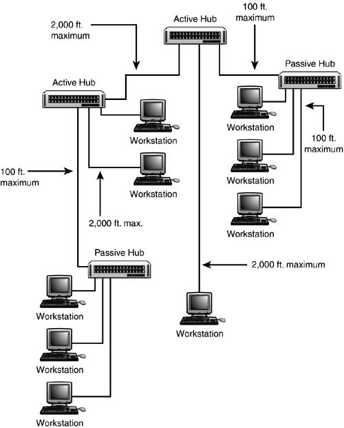
Bus and Star TopologiesEven though ARCnet is a token-passing technology, like a Token-Ring network, it can be wired in using several methods . Unlike with Token-Ring networks, no computer on the ARCnet LAN acts as a monitor to check for errors or otherwise manage the network. The reconfiguration process that ARCnet uses to form a logical ring is not directly related to the physical layout of the network. Bus TopologyThe simplest network topology that can be used for ARCnet is a bus using coaxial cables with BNC T-connectors. Up to eight nodes can be connected to any bus segment in a daisy-chain made up using the T-connectors. The total length of the segment is limited to 300 meters (1,000 feet). For such a small network, no hub would be necessary. However, as you can see in Figure 13.2, an active hub can be used to join multiple segments to create a larger LAN than can be created by using a single cable segment. A passive hub cannot be used to connect individual segments based on a bus topology; only active hubs can do this. Passive hubs can be used only to connect individual workstations. Figure 13.2. An active hub can be used to join multiple coaxial segments, and might need terminators. You also can create a bus topology using UTP cables. The UTP ARCnet adapter has two connectors, usually RJ11 or RJ45. Stations are daisy-chained from one node to the next using both connectors. In some cases, the last node on each end of the bus will need to have a terminator inserted into the last connector. Some cards provide an auto-termination feature. When using UTP, you can have as many as 10 nodes on one segment, with any repeater counting toward that limit. Each node on the bus must be separated by a minimum of about 6 feet. The total segment length can be as much as 400 feet (120 meters). Star TopologyYou can create a physical star topology by using hubs. You can create a tree structure of multiple stars by cascading hubs. Figure 13.3 shows a small network that uses both active and passive hubs, and also has workstations that connect directly to an active hub. Figure 13.3. The star topology can be extended using additional hubs. The major difference you will notice in Figure 13.3 is that, when a station connects to an active hub, the distance can be as great as 2,000 feet (500 meters). When a station connects to a passive hub, the distance shrinks to only 100 feet (30 meters). These same rules apply when connecting hubs. The passive hub connected to an active hub cannot be farther away than 100 feet. Two active hubs can be separated by as much as 2,000 feet. The capability of the active hub to regenerate the signal accounts for the longer distances achieved. The overall size of the network should never exceed 20,000 feet (6,000 meters).
Many vendors sell hubs, cables, and other network devices that can be used to create ARCnet networks that vary from these topologies and their limitations. The best source for information about vendors who supply ARCnet hardware is the ARCnet Trade Association (www.arcnet.com). ARCnet Network Adapter CardsBecause ARCnet has been around for so long, a lot of different network cards are still in use today. ARCnet cards are not interchangeable with Ethernet cards. During an upgrade, you will have to incur the cost of new NICs for each node on the network. Two main categories of cards are used in ARCnet networks: Bus NIC (high-impedance driver) and Star NIC (low-impedance driver). As their names imply, they are different in that the Bus NIC should be used on a bus topology and the Star NIC should be used on a star topology. Some newer cards can provide both options.
Connecting ARCnet LANs to Ethernet LANsBecause of the different signaling methods used and the different network access techniques, it should be obvious that you can't mix Ethernet and ARCnet nodes on the same cable. However, one of the advantages of ARCnet is that there are vendors who manufacture hubs and other devices that allow you to connect dissimilar cabled networks. For example, there are active hubs that allow for coaxial cable, twisted pair, and fiber-optic cabling. Conversion boxes are also available to bridge between an Ethernet network and an ARCnet LAN. Upper-level protocols, such as TCP/IP, can then be used to pass traffic between the two networks. |
EAN: 2147483647
Pages: 434