Asynchronous Transfer Mode (ATM)
| Asynchronous Transfer Mode was developed by AT&T Bell Labs during the 1980s. It is a connection-oriented technology, much like the public telephone system, in which a connection is established between two endpoints before the actual data exchange can begin. ATM can be used in both LAN and WAN environments and provides for full-duplex communication. The fact that many kinds of traffic are being carried on electronic networks today influenced the design of ATM. The PSTN was originally designed to carry voice communications along with other simple services, such as telex. Today, electronic networks are used to transmit data, voice, and video, and to provide connections for other kinds of multimedia applications.
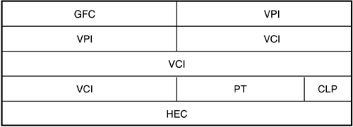
In an attempt to design a one-size-fits-all network and provide for new kinds of traffic in the future, ATM uses a fixed packet size of 53 bytes (48 bytes for the payload and 5 bytes for the header) to transmit data. In referring to a packet of data in ATM networks, the term cell is normally used. The advantage to using a fixed-length cell as opposed to a variable-length packet such as that used by Frame Relay ”discussed later in this chapter ”is that hardware devices that switch network traffic usually can be designed to operate at higher speeds when switching fixed-length packets of information. The algorithm can be implemented with less complex code and hardware design because the switch that routes cells through an ATM network doesn't have to perform calculations to determine where one packet stops and another begins, which is the case in Frame Relay networks where packet size is not fixed. The small header also means that the switch must process much less information for each packet. There are two kinds of ATM frame headers, but both are 5 bytes. During the development of ATM, some argued for a smaller cell size of 32 bytes, which would provide a better quality voice service. Others argued for a cell size of 64 bytes, which would provide more efficient data-delivery services. The 48-byte payload was finally chosen as a compromise. Add that to the 5-byte header, and you have a fixed-cell size of 53. ATM FramesATM has two types of frame headers. The first is the User -Network Interface (UNI) header, which is used for ATM cells that travel between an endpoint in the connection ”such as a standard network router or perhaps a PC or high-end workstation equipped with an ATM network card ”and the ATM switch. This frame type, shown in Figure 16.2, consists of 5 bytes divided into eight fields. Figure 16.2. Note the contents of the ATM UNI cell header. The fields of the UNI cell header are as listed here:
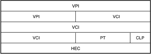
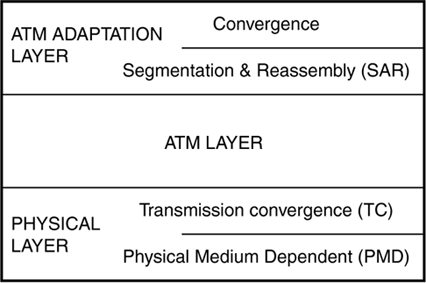
The second kind of ATM cell header is the Network-Node Interface (NNI) format. NNI is used for transmissions between the switches that make up the ATM network, which, as you can see in Figure 16.3, is similar to the UNI cell header. Figure 16.3. Note the contents of the ATM NNI cell header. The main difference from the UNI header is that the NNI cell doesn't have the GFC field. The other fields are there; the VPI field has grown from 8 bits to 12 bits, which can provide for up to 4,096 virtual paths through the network. ATM ConnectionsConnections created between endpoints in the ATM network can be either permanent virtual connections (PVCs) or switched virtual connections (SVCs) . Each switch in the ATM network keeps track of connections using routing tables, and decisions are made based on the information in the 5-byte header. Because the switch does not have to make any decisions based on the service data contained in the cell's payload section, hardware-based switches can quickly route and transport cells to their destinations. ATM provides two kinds of transport connections: virtual channels and virtual paths . A virtual channel is used for an individual connection through the network. The virtual channel identifier (VCI) is used to identify cells in this connection. A virtual path is made up of multiple virtual channels that all share a common path through the network; it is identified in the cell header by a virtual path identifier (VPI) . When connections are grouped using VPIs, management and controlling functions must be performed only once for a group of individual connections (using the VPI), making the network operate more efficiently . However, the values for the VPI/VCI fields do not remain the same when the cells travel through ATM switches. When a cell is received on one port of the switch, the VPI/VCI fields are used to perform a lookup in the routing table. When a match is found, the new VPI/VCI values are inserted into the cell and it is transmitted out on a port that gets it to its eventual destination, based on the path created during call setup (or as determined by the administrator for a PVC). To put it another way, VPI/VCI values have local significance only for the particular connection. Before any data can be exchanged, the virtual connection path must be determined. Similar to the mechanism used in the telephone network, the path through the network from one switch to another switch is predetermined before any data exchange takes place. In determining the path that the connection will use, the quality of service for the traffic is taken into consideration to ensure that a path will be created that can provide the bandwidth needed by the service. Traffic is policed to ensure that a particular connection does not abuse the network by using resources to which it is not entitled. The ATM Architecture Model (B-ISDN/ATM Model)The basic architecture used for ATM involves three layers : Physical layer, ATM layer, and ATM Adaptation layer (see Figure 16.4). Figure 16.4. The ATM architecture model. As you can see in this figure, the Physical layer is further subdivided into the Physical Medium Dependent (PMD) sublayer and the Transmission Convergence (TC) sublayer. The ATM Adaptation layer is further divided into the Segmentation and Reassembly (SAR) sublayer and the Convergence sublayer (CS). The Physical LayerThe two components of the Physical layer are responsible for the actual transmission of cells across the network. Signal encoding and interfacing with the network transmission media (such as copper wire or fiber- optic cables) are performed by the PMD. By keeping the physical aspects of the protocol as a separate component, it is possible to define many kinds of PMDs for ATM. Thus, it's easy to create a PMD to allow ATM to operate over many types of physical networks. The TC component of the physical layer interfaces with the ATM layer and is responsible for taking the stream of bits supplied by that layer and mapping the ATM cells onto the PMD-specific frame. For example, if the underlying network is SONET, the TC component maps the ATM fixed-length cells onto SONET frames and then passes these to the SONET PMD. The ATM LayerThe VPI/VCI routing functions and flow control mechanisms are implemented on the ATM layer. Remember that the combination of VPI/VCI allows for multiplexing many connections across a common virtual circuit. The ATM layer is responsible for this multiplexing- demultiplexing functionality. This layer also can monitor connections and take corrective action if it finds that a connection is not performing within the boundaries that were negotiated during call setup. Routing functions use the VPI/VCI to ensure that the cells travel over the proper connection between the connection's endpoints. However, similar to the Internet Protocol (IP), the ATM layer does not provide for error control. If packets are dropped at a switch along the connection's path, it's up to higher-level protocols to recognize this and take the necessary actions to retransmit the data. The ATM Adaptation Layer (AAL)The AAL is responsible for packaging the data on the sending part of the connection into 48-byte payloads, and for unpacking the data and reassembling it into larger messages on the receiving end. For example, an IP datagram handed down by the IP protocol will be larger than the payload size that the ATM cell can handle. In the ATM Adaptation layer, this larger message is fragmented into smaller payloads and sent down to the Physical layer for transmission in ATM cells. At the receiving end of the connection, the individual payloads are reassembled back into the larger message and passed up to a higher-level network protocol. In the Convergence sublayer (CS), a protocol data unit (PDU) from a higher-level protocol is encapsulated into a format so that it can be reassembled into that same format at the receiving end. In the Segmentation and Reassembly (SAR) sublayer, the data is divided into 48-byte payloads. These payloads then are passed to the ATM layer, which attaches the header to create the 53-byte cell. Several ATM adaptation layers have been defined by the ITU-T:
Of these layers, AAL5 was created specifically to make ATM an attractive choice for typical LAN applications. The AAL5 frame format is composed of several fields that are made up of the actual payload, followed by the AAL5 trailer fields:
If you'll remember, the third bit of the Payload Type Indicator field of the ATM header is used to specify that the cell is the last cell of a message (or PDU) that was broken down into 48-byte payloads. Thus, larger messages from higher-level protocols (such as IP) can be identified and reassembled while passing through the ATM network of switches in simple, short, 48-byte payloads. LAN Emulation (LANE)ATM was originally designed to be a wide area networking protocol. However, local area networks have changed dramatically in the past few years. Whereas a simple 10BASE-T network might have provided sufficient bandwidth a few years back, you now see LANs composed of, or connected by, much faster links, such as Gigabit Ethernet and 10 Gigabit Ethernet. Speed is not the only thing that's changed in the local area networking scene. The LAN that was used for simple file and print sharing now must support various applications. For example, videoconferencing is becoming a common application in the LAN. In a traditional LAN, however, you can't "reserve" or "guarantee" that the bandwidth needed to support such an application will always be available. Using ATM in a LAN can help reduce congestion if the network consists of multiple kinds of traffic, such as one that supports workstations and file servers along with multimedia applications. If you use ATM as a backbone, you can interface it with your normal Ethernet or Token-Ring segments. The ATM Forum has published specifications for LANE to define the approach to be taken for using ATM in the LAN environment. LANE specifies how other traditional LAN protocols ”such as Ethernet (IEEE 802.3) and Token-Ring (IEEE 802.5) ”are to be carried over ATM. The LANE protocol was developed to allow a LAN to be emulated using ATM. That is, LANE makes an ATM switched network look to the client computer just like a typical LAN. LANE consists of the following:
LANE can be used with Ethernet and Token-Ring networks to provide a faster connection for your LAN because all traffic is sent through ATM switches. You can find many ATM switches that include support for LANE, or, as is the case with Windows 2000 or Windows Server 2003, the LAN Services component can reside on a Windows 2000/2003 Server. IP over ATMFor most implementations , you'll find that AAL5 is used to send IP datagrams over ATM. The relevant RFC documents are RFC 1577, "Classical IP and ARP over ATM," and RFC 1626, "Default IP MTU for use over ATM AAL5." RFC 1577 doesn't define how ATM networks function, but provides instead a method for IP and address resolution mechanisms over an ATM network. RFC 1626 defines the value of 9,180 bytes as the default Maximum Transmission Unit (MTU) size for IP datagrams on an ATM network. It also discusses how, during call setup for a switched virtual circuit, the actual MTU size used for the connection can be negotiated. When IP datagrams are sent over an ATM connection, the AAL5 trailer information is added to the end of the datagram and then passed to the SAR sublayer for division into the 48-byte payloads required for ATM. As explained in the preceding section, when the cell containing the last part of the IP datagram is created, the third bit of the PT (Payload Type) is set to 1 so that the endpoint recognizes that it now has all the information necessary to reassemble the smaller payloads into the original IP datagram. IP over ATM has several advantages that make it a better choice for IP networks than LANE. First, LANE doesn't support the QoS capabilities of ATM, which you'll learn about in the next section. Second, IP over ATM has a lower overhead, so more bandwidth is available for transmitting actual data. Windows 2000 and Windows Server 2003 also support IP over ATM. Because of this, IP over ATM usually is faster than LANE. Similar to LANE, the IP over ATM software interfaces between the TCP/IP protocol stack and the ATM network. ATM Service CategoriesAlthough early implementations of ATM use the technique of reserving a specified, fixed amount of bandwidth for a connection in advance, service categories now allow for several levels of service that can be matched to the needs of different types of traffic. Each level of service defines the network behavior for a different kind of network traffic that can be used to specify the QoS required for certain kinds of applications. For example, some network applications require precise timing and cannot tolerate excessive delays or reductions in bandwidth (such as video transmissions). Other applications tend to make bursty requests when bandwidth requirements vary widely in just a short time (such as file transfers). The following service categories are presently defined by the ATM Forum:
The CBR category is based on providing a constant maximum bandwidth allocation for the connection for time-sensitive applications. The application does not always have to use the maximum bandwidth, but the maximum is available if needed for this level of service. This service category is suitable for use by real-time applications, voice and video applications, videoconferencing, and other similar applications. The rt-VBR service category also is meant to provide a high level of service for time-sensitive applications that do not always maintain a constant bit rate but are still time-sensitive applications. The nrt-VBR service category is similar to the rt-VBR category in that the expected traffic will be bursty in nature, but the nature of the communications does not require that data be delivered without significant delays. Both VBR categories can be useful for applications such as voice, when compression techniques are used, and possibly transaction-based applications, such as reservation systems or for carrying Frame Relay traffic. The ABR category is intended for applications that might increase or decrease their traffic level depending on network conditions. In other words, they can be satisfied by using whatever bandwidth is available. Connections of this type can specify a minimum required bandwidth level but then can use more bandwidth as the network makes it available. Typical uses for this kind of service are LAN connections, such as distributed file services. The UBR service category represents a "best effort" connection and is intended for applications that really don't care about bandwidth or QoS. This bottom-of-the-barrel kind of service is useful for applications with traffic that needs to get from one place to another but is in no hurry; for example, file transfers that can be done in a batch mode and do not have users sitting at the keyboard waiting for completion. Messaging services, such as email, also might find this service level sufficient. |
EAN: 2147483647
Pages: 434


