9.5 Burst Profile Usage: DCD Message and the DIUC Indicator
9.5 Burst Profile Usage: DCD Message and the DIUC Indicator
In this section, the mechanism for burst profile transmission and the main parameters required for this operation are described. A burst is a contiguous portion of data stream using the same PHY parameters. These parameters are modulation type, Forward Error Correction (FEC) type, preamble length, etc. (see below), and are known as the burst profile. This type of multiplexing is known as TDM (Time Division Multiplexing) in 802.16. Each burst profile is indicated by its Downlink Interval Usage Code (DIUC) or Uplink Interval Usage Code (UIUC) for the downlink and uplink respectively.
9.5.1 Burst Profile Selection Thresholds
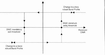
The burst profile attributes were described in Chapter 6. The main parameter is the Modulation and Coding Scheme (MCS) used in the burst. In addition, and as seen in Chapter 6 and Annex B, two CINR threshold numerical values are provided with each burst profile description: the DIUC mandatory exit threshold and the DIUC mandatory entry threshold. These two thresholds are used for the selection of one of the defined (in the DCD message) burst profiles, based on the received CINR. The procedure is illustrated in Figure 9.12 and stated below:
-
If CINR ≤ DIUC mandatory exit threshold → this DIUC can no longer be used → change to a more robust DIUC is required.
-
If CINR ≥ DIUC minimum entry threshold →this DIUC can be used → change to a less robust DIUC.

Figure 9.12: Use of thresholds for a given burst profile.
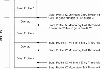
The possible thresholds values for neighbouring burst profiles are shown in Figure 9.13. The downlink burst profile is determined by the BS according to the quality of the signal that is received by each SS. While operating on a given burst profile, the SS monitors its received CINR and compares the average value with the allowed range of operation. This region is bounded by the two threshold levels of the burst profile used. These two threshold levels are defined along with the burst profile in the DCD message.

Figure 9.13: Illustration of burst profile threshold values for three neighbouring profiles. Burst profile X is the most robust. (From IEEE Std 802.16-2004 [1]. Copyright IEEE 2004, IEEE. All rights reserved.)
If the received CINR goes outside the allowed operating region (from the top or from the bottom), the SS must request a change to a new burst profile, according to the principle given above in this subsection and using one of two proposed methods (described in Chapter 11). This depends on whether this SS has been given an uplink data grant allocation or not.
9.5.2 DCD (Downlink Channel Descriptor) Message
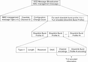
The DCD (Downlink Channel Descriptor) message is a broadcasted MAC management message transmitted by the BS at a periodic time interval in order to provide the burst profiles (physical parameter sets) that can be used by a downlink physical channel during a burst, in addition to other useful downlink parameters. The general format of a DCD messages is shown in Figure 9.14. The contents of the DCD message fields are now given.

Figure 9.14: General format of the DCD (Downlink Channel Descriptor) message
The Downlink Channel ID (ChID, not to be confused with CID) is the identifier of the downlink channel to which this message refers. This identifier is arbitrarily chosen by the BS and is unique only within the MAC domain. This acts as a local identifier for transactions such as ranging.
The Configuration Change Count (CCC) is an 8 bits field, incremented by one (modulo 256) by the BS whenever any of the values of the DCD message changes. If the value of this count in a subsequent DCD remains the same, the SS can decide, after reading the CCC field, that the remaining fields have not changed. The SS may then disregard the remainder of the DCD message.
The Downlink_Burst_Profile fields describe each of the burst profiles that can be used in the downlink until the next DCD message. The Downlink_Burst_Profile field contents are defined separately for each PHY specification (Single Carrier, OFDM, OFDMA, etc.). Table 9.3 defines the format of the Downlink_Burst_Profile encoding, which is used in the DCD message of the OFDM (WiMAX) interface. This is the format shown in Figure 9.14. The Downlink_Burst_Profile includes a TLV encoding (see Section 8.6) that defines and associates with a particular Downlink Interval Usage Code (DIUC) value, the PHY characteristics (burst profile) used with that DIUC. Within each downlink burst profile is a list of PHY attributes (burst profile encodings) for that burst profile, encoded as TLV values.
| Field | Size |
|---|---|
| Type = 1 | 8 bits |
| Length | 8 bits |
| Reserved | 4 bits |
| DIUC | 4 bits |
| TLV encoded information | Variable |
The TLV encoded information of a burst profile is made of two fields (see Figure 9.14):
-
Channel encodings. The main parameters are the BS EIRP (Effective Isotropic Radiated Power), the TTG (Tx/Rx Transition Gap) and the RTG (Receive/transmit Transition Gap), the BS ID, the frame duration, etc. See the example in Section 9.5.4.
-
The downlink burst profile number i encoding. This indicates the type of modulation and channel coding and the received signal thresholds required for using this profile, which will be indicated by DIUC #i. As already mentioned, four modulations can be used (BPSK, QPSK. 16-QAM and 64-QAM) with four possible coding types (RS, CC, BTC and CTC). Table 9.4 shows possible values of a burst profile as defined by the 802.16 standard for the OFDM PHYsical interface.
| Name | Value | |
|---|---|---|
| FEC code type | 0 = BPSK (CC) 1/2 | 11 = 64-QAM (BTC) 213 2/3 |
| 1 = QPSK (RS + CC/CC) 1/2 | 12 = 64-QAM (BTC) 5/6 | |
| 2 = QPSK (RS + CC/CC) 3/4 | 13 = QPSK (CTC) 1/2 | |
| 3 = 16-QAM (RS + CC/CC) 1/2 | 14 = QPSK (CTC) 2/3 | |
| 4 = 16-QAM (RS + CC/CC) 3/4 | 15 = QPSK (CTC) 3/4 | |
| 5 = 64-QAM (RS + CC/CC) 2/3 | 16 = 16-QAM (CTC) 1/2 | |
| 6 = 64-QAM (RS + CC/CC) 3/4 | 17 = 16-QAM (CTC) 3/4 | |
| 7 = QPSK (BTC) 1/2 | 18 = 64-QAM (CTC) 2/3 | |
| 8 = QPSK (BTC) 3/4 or 2/3 | 19 = 64-QAM (CTC) 3/4 | |
| 9 = 16-QAM (BTC) 3/5 | 20–255 = Reserved | |
| 10 = 16-QAM (BTC) 4/5 | ||
| DIUC mandatory exit threshold | The CINR at or below where this DIUC can no longer be used and where a change to a more robust DIUC is required. Expressed in 0.25 dB units. See Section 9.5.1. | |
| DIUC minimum entry threshold | The minimum CINR required to start using this DIUC when changing from a more robust DIUC is required. Expressed in 0.25 dB units. See Section 9.5.1. | |
9.5.3 Transmission of the DCD Message
For all 802.16 PHYsical Layers, the maximum value of the time between the transmissions of two consecutive DCD messages (or two consecutive UCD messages) is 10 s. For OFDM and OFDMA PHY, the frame duration is between 2 ms and 20 ms (although all the possible values are not necessarily mandatory for WiMAX profiles).
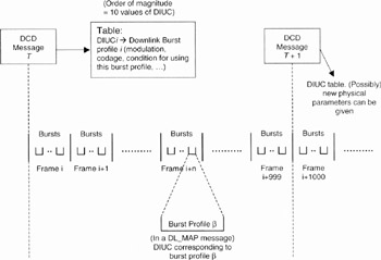
It can then be concluded that a non-DCD-including frame is transmitted more frequently than a DCD message. As already mentioned, each frame may contain many bursts, each burst having a uique DIUC. Therefore, each DCD message will concern a large number of frames and an even larger number of bursts (see Figure 9.15).

Figure 9.15: Illustration of the DCD message transmission period and DIUC use. The value of 1000 frames between two DCD messages is an order of magnitude.
9.5.4 An Example of the DCD Message
An example will now be given of a DCD MAC management message. In this message, two burst profiles are defined and associated with DIUC 0101 (hexadecimal: 5) and DIUC 1010 (hexadecimal: A).
The global parts of this message are shown in Table 9.5. The full details of this message, including fields lengths, are given in Annex B. For this message the OFDM PHYsical interface specificatios are considered. 802. 16e added new parameters to the DCD message (mainly for handover process); they are not taken into account in this example.
9.5.5 DIUC Values
The DIUC (Downlink Interval Usage Code) is then the indicator of a burst profile, i.e. the PHY characteristics (modulation, encoding, burst profile use condition, etc.) of a downlink burst. The DIUC is a 4-bit field. The value of DIUC is PHY layer-dependent. Table 9.6 shows the values defined for the OFDM (WiMAX) PHY Layer. Only 11 values are used for burst profile selection. The correspondence between the 20 modulation and coding scheme possibilities shown in Table 9.5 and the DIUC value (a maximal number of 11 burst profile value indicators) is the choice of the BS.
| Field contents | Description |
|---|---|
| MAC management message Type (= 1) | Identification of the MAC management message = DCD |
| Downlink Channel ID Configuration Change Count Type = 1 | Indication of possible DCD change Start of downlink burst profile 0101 (OFDM PHY Layer format) |
| Length Reserved DIUC = 0101 | DIUC value indicating this burst profile Start of downlink burst profile 0101 channel encodings (OFDM PHY Layer format) |
| TLV of downlink burst profile 0101, indicating the length of this object | |
| TLV of the BS transmitted power | |
| TLV of the TTG (transmit burst/receive burst transition gap) | |
| TLV of Base Station ID | |
| TLV of Frame Duration | |
| Other TLVs of downlink burst profile 0101 channel encodings | |
| TLV of downlink frequency | Start of downlink burst profile 0101 burst profile encodings (OFDM PHY Layer format) |
| TLV of coding and modulation scheme (called FEC code) | |
| TLV of DIUC selection thresholds | |
| Other TLV of downlink burst profile 0101 burst profile encodings | |
| Type = 1 | Start of downlink burst profile 1010 (OFDM PHY Layer format) |
| Same fields as for downlink burst profile 0101 (with possible different values) |
| DIUC | Usage |
|---|---|
| 0 | STC zone |
| 1-11 | Burst profiles |
| 12 | Reserved |
| 13 | Gap |
| 14 | End of Map |
| 15 | Extended DIUC |
Each interval or, more specifically, burst (downlink or uplink) will have its burst profile and start time described by a DL-MAP IE (Downlink MAP Message Information Element) or a UL-MAP IE. The DL-MAP and the UL-MAP are MAC management messages that describe the use of the time frame by different SSs (see above). The burst profile is referenced by the DIUC value. Only bursts whose profile is explicitly known, which is the case for some control bursts (example: FCH burst, see above), do not have a burst profile DIUC value.
The DIUC possible values, other than burst profiles, shown in Table 9.6 are the following:
-
STC (Space-Time Coding) is a transmission technique used to decrease multipath effects. The modulation used is QPSK.
-
Gap is a period of time between the downlink burst and the subsequent uplink burst or between the uplink burst and the subsequent downlink burst. This gap allows time for the BS or the SS to switch from transmits to the receive mode and inversely.
-
An End of Map IE terminates all allocations in an IE list. The end of the last allocated burst is indicated by allocating an End of Map burst.
-
Extended DIUC. A DIUC value of 15 indicates that the IE carries special information. An Extended DIUC field, on 4 bits, is then present, showing the extended DIUC signification (see Table 9.7 for the OFDM PHYsical Layer).
| Extended DIUC value | Possibility usage |
|---|---|
| 0 × 00 | Issued by the BS to request a channel measurement report. The Channel_Measurement_IE is followed by the End of Map IE |
| 0 × 01 | Indicates that the subsequent bursts utilise a preamble which is cyclically delayed in time by M samples (Physical Modifier IE) |
| 0 × 02 | Switch from non-AAS to AAS-enabled traffic. AAS, Adaptive Antenna System (see Chapter 12) |
| 0 × 03 | Specify one of a set of parallel downlink bursts for transmission (concurrent transmission IE format) |
| 0 × 04 | Indicate that the subsequent allocations, until the end of the frame, are STC encoded |
| 0 × 05 | Indicate that subsequent allocations use downlink subchannelisation (for a downlink subchannelisation-enabled BS) |
| 0 × 06→0 x 0F | These extended DIUC values are called the Dummy IE. Left for future specifications |
An SS will ignore an IE with an extended DIUC value for which the station has no knowledge (e.g. an SS that has no support for STC). In the case of a known extended DIUC value, but with a length field longer than expected, the SS processes the information up to the known length and ignores the remainder of the IE.
Table 9.8 shows the values defined for the OFDMA (WiMAX) PHY Layer. A disadvantage of an OFDM transmission is that it can have a high PAPR (Peak to Average Power Ratio). The PAPR is the peak value of transmitted subcarriers to the average transmitted signal. A high PAPR represents a hard constraint for some devices (such as amplifiers). DIUC = 13 may be used for the allocation of subchannels for PAPR reduction schemes. The subcarriers within these subchannels may be used by all SSs to reduce the PAPR of their transmissions. The SS will ignore the received signal (subcarriers) in the GAP/PAPR reduction region.
| DIUC | Usage |
|---|---|
| 0-12 | Burst profiles |
| 13 | Gap/PAPR |
| 14 | Extended-2 DIUC |
| 15 | Extended DIUC |
9.5.6 UCD (Uplink Channel Descriptor) Message and UIUC Indicator
The UCD (Uplink Channel Descriptor) message is a broadcasted MAC management message transmitted by the BS at a periodic time interval in order to provide the burst profile (physical parameter sets) description that can be used by an uplink physical channel in addition to other useful uplink parameters. Its functioning is very similar to the DCD so will not be described in as much detail.
A UCD message must be transmitted by the BS at a periodic interval in order to define the characteristics of an uplink physical channel. The maximum allowed value for this period is 10 s (as for DCD). The UCD message of OFDM PHY includes the following parameters:
-
Configuration Change Count. This is the same as for DCD.
-
Ranging Backoff Start and Ranging Backoff End (8 bits each). These are initial backoff and final (or maximum) backoff window sizes for initial ranging contention (see Chapter 11), expressed as a power of 2. Values of these exponents are in the range 0–15.
-
Request Backoff Start and Request Backoff End (8 bits each). These are initial backoff and final (or maximum) backoff window sizes for contention BW (bandwidth) requests (see Chapter 10), expressed as a power of 2. Values of these exponents are in the range 0–15.
-
For each uplink burst profile defined in this UCD message, Uplink_Burst_Profile, which is a compound TLV encoding that defines and associates with a particular UIUC, the PHY characteristics that must be used with that UIUC. The TLV encoded values of a burst profile are globally similar to the ones of the downlink burst profiles in the DCD message. The following ones are burst profile parameters specific to UCD.
-
Contention-based reservation timeout. This is the number of UL-MAPs received before a contention-based reservation is attempted again for the same connection.
-
Bandwidth request opportunity size. This is the size (in units of PS) of the PHY payload that an SS may use to format and transmit a bandwidth request message in a contention request opportunity. The value includes all PHY overhead as well as allowance for the MAC data the message may hold.
-
Ranging request opportunity size. This is the size (in units of PS) of the PHY bursts that an SS may use to transmit a Ranging Request message in a contention ranging request opportunity (see Chapter 11). The value includes all PHY overheads and (in addition to the bandwidth request opportunity size content) the maximum SS/BS round trip propagation delay.
-
Subchannelisation REQ Region-Full Parameters. This is the number of subchannels used by each transmit opportunity when REQ Region-Full is allocated in a subchannelisation region. Possible values are between 1 and 16 subchannels (see Section 10.4).
-
Subchannelisation focused contention codes. This is the number of contention codes (CSE) that can be used to request a subchannelised allocation. The default value is 0 (no subchannelised focused contention). Allowed values are between 0 and 8. Focused contention is described in Section 10.4.
As for the DIUC and the DCD, the UIUC (Uplink Interval Usage Code) is defined as an indicator of one of the uplink burst profiles described in the UCD. The UIUC is a 4-bit field corresponding to 16 possible values. The value of UIUC is PHY layer-dependent. Table 9.9 shows the UIUC values defined for the OFDM (WiMAX) PHY layer. Only eight values are used for burst profile selection. The UL-MAP IE for allocation of bandwidth in response to a subchannelised network entry signal (see Chapter 10), in the subchannelised section of the UL-MAP, is identified by UIUC = 13. An SS responding to a bandwidth allocation using the subchannelised network entry IE starts its burst with a short preamble and uses only the most robust mandatory burst profile in that burst.
| UIUC | Usage |
|---|---|
| 0 | Reserved |
| 1 | Initial ranging |
| 2 | REQ (Request) region full |
| 3 | REQ (Request) region focused |
| 4 | Focused contention IE |
| 5–12 | Burst profiles |
| 13 | Subchannelisation network entry |
| 14 | End of Map |
| 15 | Extended UIUC |
There are 20 available modulation and coding schemes for uplink burst profiles. The most robust is BPSK with a channel coding rate of 1/2 and the less robust being 64-QAM with a coding rate of 5/6 (both OFDM and OFDMA layers). The correspondence between these 20 available modulation and coding schemes for uplink burst profiles and the UIUC value is the choice of the BS. Only eight UIUC values can be used as indicators of uplink burst profiles (equivalently, only eight uplink burst profiles may be defined in an UCD).
Many of the UIUC values shown in Table 9.9 will be used in the following chapters. The initial ranging process is described in Chapter 11. Uplink bandwidth request procedures (concerning UIUC values 2 to 4) are described in Chapter 10. The value 13 of UIUC corresponds to the subchannelised network entry IE, used in the procedure of subchannelisation network entry. Extended DIUC allows additional functions. For example, when a power change for the SS is needed, UIUC = 15 is used with an extended UIUC set to 0 x 00 and with an 8-bit power control value. This power control value is an 8-bit signed integer expressing the change in power level (in 0.25 dB units) that the SS must apply to correct its current transmission power.
For OFDMA PHY, the sounding zone is a region of one or more OFDMA symbol intervals in the uplink frame that is used by the SS to transmit sounding signals to enable the BS to determine rapidly the channel response between the BS and the SS. The BS may command an SS to transmit a sounding signal at one or more OFDMA symbols within the sounding zone by transmitting the UL-MAP message UL_Sounding_Command_IE() to provide detailed sounding instructions to the SS. In order to enable uplink sounding, in UL-MAP, a BS transmits UIUC = 13 with the PAPR_Reduction_Safety_and_Sounding_Zone_Allocation_IE() to indicate the allocation of an uplink sounding zone within the frame.
EAN: 2147483647
Pages: 124