IDSIPS Deployments
IDS/IPS Deployments
The most critical part of intrusion detection and prevention is the proper deployment and placement of your sensors. An IDS/IPS is only going to be effective if it is deployed in such a manner that it can monitor the traffic that is of concern.
Figure 4-1 illustrates how you would connect two IDS sensors to your network to monitor the traffic entering and exiting your Internet DMZ segment as well as the traffic in front of your firewall. The monitoring interfaces are connected to switches, which mirror the traffic from the ports that the firewall is connected on to the ports that the IDS is connected on. The management interfaces are connected back to the internal network (preferably on a management subnet), allowing the IDS sensors to be managed by a central management console.
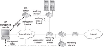
Figure 4-1: Connecting your IDS/IPS to the network
Detection vs. Prevention
Throughout this chapter, I have referred to intrusion detection and intrusion prevention as almost the same thing. In truth, there are many similarities between the two; however, they are two distinct products with unique roles in your environment.
Intrusion detection is just that, detection. As mentioned earlier in this chapter, intrusion detection is largely a process of implementing an alarm system throughout your network to notify you of situations that warrant further investigation. Intrusion detection is best suited for application throughout your network to monitor traffic at specific choke points, such as backbone segments.
Intrusion prevention takes detection a step further and follows the mantra, If we have detected suspicious traffic, let s prevent it from accessing the network or host. Intrusion prevention seeks to actively stop an intrusion from occurring, as opposed to passively alarming as to its occurrence. On the surface, this sounds like a great thing.
In practice, however, IPS often misses the mark because the detection process is not a perfect science. There are still far too many false positives that can occur in the detection process, and a misconfigured IPS can take a false positive and create one of the very same things it is trying to prevent ”a denial of service by preventing legitimate traffic from being permitted.
Sensor Placement
Attacks originate from both internal and external sources. As a result, it is important to locate your intrusion detection and prevention systems where they can monitor not only external traffic, but internal traffic as well. Because of this requirement, you need to plan on IDS/IPS being a system of devices, not a singular device. The following locations are recommended locations for IDS/IPS sensors:
-
In front of your external firewall Although there is some debate as to the value of placing a sensor outside your firewall, I recommend it so that you can gain some kind of insight as to what is happening that your firewall is protecting you from. The sensor should be configured to monitor the traffic on the switch port that the firewall is connected to. When you implement the IDS/IPS in this location, I recommend that you significantly tune down the alerts because much of this traffic should be blocked by the firewall.
-
Behind your firewalls that provide access to DMZ or internal networks This is the most common location for sensor placement because these network connections represent choke points where all traffic between network modules must pass. The sensor should be configured to monitor the traffic on the switch port that the firewall is connected to. When you implement the IDS/IPS in these locations, I recommend that you configure the sensor to monitor and alarm on any suspicious traffic, because an alarm at this point means that the traffic has bypassed the firewall in some way.
-
Integrated into your gateway devices Many gateway devices, such as firewalls, have IDS and in particular IPS functionality built in. This is the location where I recommend most IPSs be implemented, because the firewall is already providing blocking functionality, and the IPS function merely extends that functionality.
-
Behind your VPN concentrators VPNs represent an easy way for harmful traffic to enter your network. This is due to the fact that often the remote connection does not implement the same degree of security that your internal network enjoys (for example, due to a laptop user who hasn t patched their laptop). You should place the IDS/IPS sensor behind the VPN concentrators so that it can monitor the unencrypted traffic as it passes to and from the VPN connections. This is important because if you place the IDS/IPS in front of the concentrator, you will not be able to gather any valid information because the data is encrypted.
-
In front of your server segments Because your servers generally contain the most valuable data in your environment, you should implement an IDS/IPS in front of your server segment to monitor the traffic passing to and from the server segment. The easiest way to do this is to configure the monitoring interface to monitor the traffic on the switch port that connects the server segment to the rest of the network.
-
Behind your WAN connections With the nature of worms, WAN connections represent an easy point for them to spread. As a result, I recommend that you implement an IDS/IPS to monitor the traffic that is passing through your WAN connections. You should configure the monitoring interface to monitor the traffic on the switch port that connects the WAN router to the internal network.
-
On your extranet connections Because extranet connections imply a connection to a remote network that you probably do not have administrative control over, you should make extensive use of IDS/IPS sensors. The first location to implement a sensor is between the extranet partner and the shared resources, typically monitoring the traffic on the switch port that connects the extranet segment to the external partner network. The second location to implement a sensor is between the internal network and the extranet segment. This is typically done by monitoring the traffic on the switch port that connects the extranet segment to the internal network.
-
On any segment that contains or connects to critical resources This is the generic catchall bullet. You should implement sensors anywhere else in your network where you have valuable resources or want a more granular idea of the kinds of traffic being passed.
Network diagrams illustrating sensor placement are provided in Chapters 11 and 12.
Sensor Placement in a Switched Network Infrastructure
One of the most confusing aspects of sensor placement is implementing them in a switched network. As you know, the whole purpose of a switched network is to prevent systems on one port from receiving traffic destined for systems on another port. This creates a problem because the sensor needs to be able to monitor all traffic passing for a given segment if you want it to be effective. You can address this, however, by connecting the sensor monitoring interface to a switch port that is configured to receive mirrored traffic from the switch ports that you want to monitor traffic on. This is referred to as a Switched Port Analyzer (SPAN) by Cisco; other vendors simply refer to it as port mirroring.
You can implement SPAN on a CATOS-based switch by running the following command at the CLI:
switch03> (enable) set span 1/1 2/1
In this example, SPAN is configured to mirror the traffic from interface 1/1 to the destination interface 2/1, where the sensor is connected.
You can implement SPAN on IOS-based switches by running the following command at the CLI:
switch02(config)#monitor session 1 source interface Fa0/1 switch02(config)#monitor session 1 destination interface Fa0/5
In this example, SPAN is configured to mirror the traffic from interface Fa0/1 to interface Fa0/5, where the sensor is connected. Although this example shows a one-to-one mirror, it is common to mirror multiple ports to a single monitoring port.
Another issue with implementing sensors on a switched network occurs when you want the sensor to be able to block unauthorized traffic. Many switches prevent a monitoring port from being able to send traffic. The sensor, however, needs to be able to transmit the countermeasure packet (typically, a spoof of the original source MAC address) in order to block the session. In addition, because the sensor is going to spoof the MAC address of the system that it is trying to protect, the switch needs to be configured to disable MAC learning on the monitoring port. If you do not do this, the switch will send all traffic for the destination system to the sensor until the server transmits and causes the switch to relearn the port that it is connected to. You can configure this on your CATOS-based switches by running the following command at the CLI:
switch03> (enable) set span 1/1 2/1 inpkts enable learning disable
EAN: N/A
Pages: 125