Section 3.2. Conventional Pulse-Detection Techniques
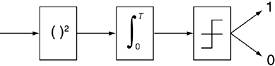
3.2. Conventional Pulse-Detection Techniques3.2.1. Energy DetectorsEnergy detectors are simple, noncoherent receivers that detect the energy of a signal and compare it with a threshold level to demodulate the data bits. Figure 3-1 shows the block diagram of an elementary energy detector receiver. Figure 3-1. Noncoherent energy detector receiver
As shown in Figure 3-1, energy detector receivers are composed of a squaring device, followed by a finite integrator and a decision threshold comparator. If the signal is present, its energy is calculated by squaring the signal. Once this energy passes a certain threshold, the data is demodulated as a digital bit 1. Consequently, if the data is not present or its energy does not pass the threshold, the received data will be demodulated to 0. 3.2.2. Classical Matched FiltersThe classical matched filter is a simple and optimal method for detecting a signal in random noise based on the correlation process. Before we go into the details of CMFs, it's worth explaining what correlation is. Correlation is a mathematical operation that provides a measure of similarity between two signals. This technique is used often in all types of pattern-recognition and signal-processing problems. The basic idea of correlation is to multiply the two waveforms at different points in time and to find the area under the curve formed by multiplication using integration in finite time. Equation 3-1 shows the mathematical expression of the correlation function. Equation 3-1
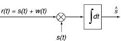
where the two signals being compared are x(t) and y(t), t is the time shift to provide sliding of y(t) on x(t), and Rxy (t) is called the correlation function. Large values for the correlation function (either positive or negative) represent strong resemblance between the two waveforms; small values close to zero represent low correlation or slight similarity between the two. In a matched filter, the received signal is correlated with a template signal matched to the transmitted signal. If the received signal is similar to the template, high correlation values are expected and the received signal can be detected. Figure 3-2 shows the block diagram of a matched filter. Figure 3-2. Classical matched filter block diagram
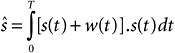
As shown in Figure 3-2, classical matched filters perform the correlation operation on the received signal r(t), which comprises the transmitted signal s(t) and channel noise w(t). The correlation operation is achieved by multiplying the received signal with a predefined template (similar to the transmitted signal), s(t), and then integrating over a finite period of time. This process maximizes the received signal's signal-to-noise ratio (SNR) and detects the desired signal from the background random noise. The following equations illustrate the matched filters operation mathematically. Equation 3-2
Equation 3-3
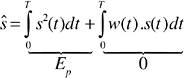
Equation 3-4
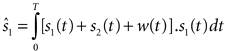
Expanding the integral in Equation 3-3 produces two terms in Equation 3-4. The first term represents the signal energy, Ep , resulting from the correlation of the transmitted signal with the similar template signal. The second term results from the correlation of the signal with noise and can be ignored due to poor correlation between the transmitted signal and the random noise. Therefore, when the filter is matched to the shape of the transmitted signal, the output of a matched filter provides sufficient statistics to detect signals in the presence of noise. It's important to emphasize that matched filters are optimal solutions only for detecting signals in the presence of additive white Gaussian noise (AWGN).[1] These receivers are suboptimal when the signal is distorted by other forms of interference, such as multiple-access interference (MAI) or narrowband interference (NBI), that do not have AWGN features. The following equations show suboptimal performance of a matched filter in a two-user system where the received signal,r(t) , consists of User 1's signal, s1(t) , User 2's signal, s2(t) , and random noise, w(t).
Equation 3-5
Assuming that User 1's signal is the desired signal, s1(t) will be multiplied with the received signal and will be integrated over a finite time. Equation 3-6
Equation 3-7
As shown in Equation 3-7, although we can ignore correlation between the desired signal and random noise, the correlation between s1(t) and s2(t) , known as MAI, cannot be disregarded and can significantly deteriorate the performance of CMFs in multiple-access systems. Therefore, modulation schemes considered for multiple-access channels should minimize the overlap of unwanted signals on the desired signal in order to use CMF receivers successfully. In Section 3.4, we present a detailed discussion of UWB modulation schemes for multiple-access channels. |
EAN: 2147483647
Pages: 93