6.7 Turbo Multiuser Detection in Space-Time Block-Coded Systems
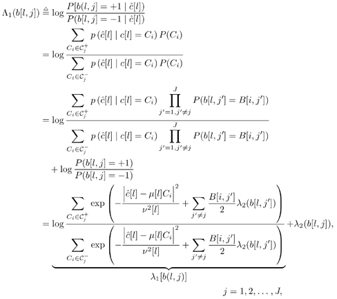
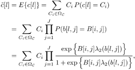
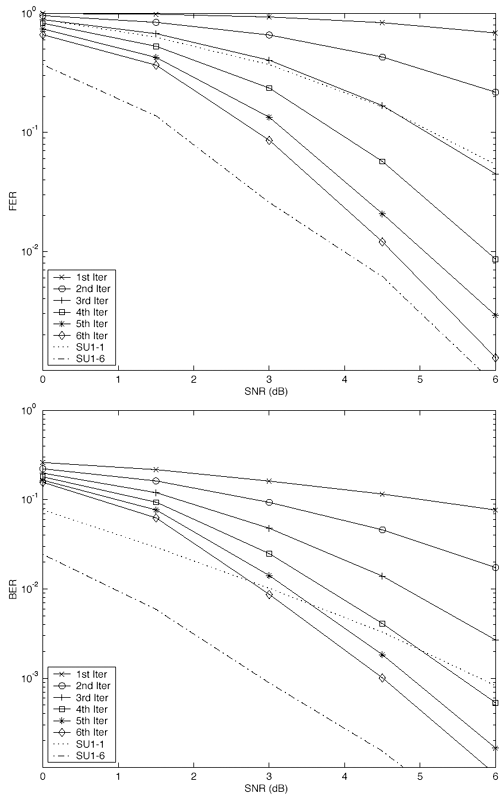
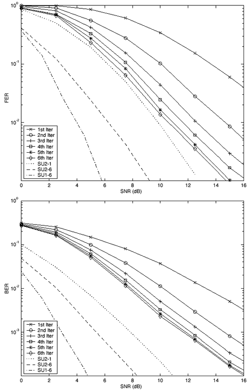
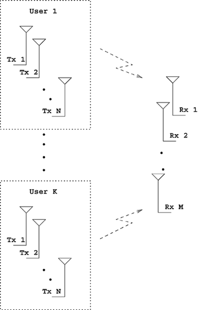
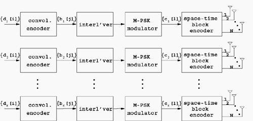
| The recently developed space-time coding (STC) techniques [350] integrate the methods of transmitter diversity and channel coding and provide significant capacity gains over traditional communication systems in fading wireless channels. STC has been developed along two major directions: space-time block coding (STBC) and space-time trellis coding (STTC). The common features of STBC and STTC lie in their realizations of spatial diversity (i.e., both methods transmit a vector of complex code symbols simultaneously from multiple transmitter antennas). Their differences, on the other hand, lie in their realizations of temporal diversity: In STBC, the temporal constraint is represented in matrix form; whereas in STTC, the temporal constraint is represented in the form of a trellis tree, which is akin to the trellis-coded modulation (TCM) code. From the coding perspective, the single- user performance of STBC and STTC has been studied in [476, 477], and some code design criteria have been developed. However, in wireless communication systems, sharing the limited radio resources among multiple users is inevitable. Indeed, the emerging wireless systems with multiple transmitter and receiver antennas enable a new dimension for multiple accessing: space-division multiple access (SDMA) [492], which when employed with the more conventional TDMA or CDMA techniques, can substantially increase system capacity. However, if not properly ameliorated, the presence of multiuser interference can significantly degrade receiver performance as well as system capacity. Therefore, the development of efficient detection and decoding techniques for multiuser STC systems ( illustrated in Fig. 6.21) is the key to bringing STC techniques into the practical arena of wireless communications. Research results along this direction first appeared in [349, 476], where some techniques for combined array processing, interference cancellation, and space-time decoding for multiuser STC systems were proposed. Figure 6.21. Multiuser wireless communication system employing multiple transmitter and receiver antennas. There are K users in the system, each user employing N transmitter antennas. At the receiver side, there are M receiver antennas. In this and the following sections we discuss turbo receiver structures for joint detection and decoding in multiuser STC systems, based on the techniques developed in previous sections. Such iterative receivers and their variants, which were first developed in [288], are described for both STBC and STTC systems. During iterations, extrinsic information is computed and exchanged between a soft multiuser demodulator and a bank of MAP decoders to achieve successively refined estimates of the users' signals. Further developments of low-complexity turbo structures for multiuser STTC systems are given in [217]. 6.7.1 Multiuser STBC System The transmitter end of a multiuser STBC system is shown in Fig. 6.22. The information bit stream for the k th user, { d k [ n ]} n , is encoded by a convolutional encoder; the resulting convolutional code-bit stream { b k [ i ]} i is then interleaved by a code-bit interleaver. After interleaving, the interleaved code-bit stream is then fed to an M -PSK modulator , which maps the binary bits into complex symbols { c k [ l ]} l , where Figure 6.22. Transmitter structure for a multiuser STBC system. STBC was first proposed in [12] and was later generalized systematically in [476]. Following [476], the k th user's STBC is defined by a P x N code matrix As a simple example, we consider a particular user employing a 2 x 2 STBC (i.e., P = 2, N = 2). Its code matrix Equation 6.184 The input to this STBC is the code vector c = [ c [1] c [2]] t . During the first time slot, the two symbols in the first row of We assume a flat-fading channel between each transmitter “receiver pair. Specifically, denote a m,n as the complex fading gain from the n th transmitter antenna to the m th receiver antenna, where a m,n ~ N c (0, 1) is assumed to be a zero-mean circularly symmetric complex Gaussian random variable with unit variance. It is also assumed that the fading gains remain constant over an entire signal frame, but they may vary from one frame to another. In general, we consider an STBC system with K users, each employing N transmitter antennas. At the receiver side, there are M receiver antennas. In this case, the received signal can be written as Equation 6.185 In (6.185), As a simple example, consider a single-user ( K = 1) STBC system with two ( N = 2) transmitter antennas and M receiver antennas, employing the code matrix g 1 in (6.184), the received signal at the m th receiver antenna for this single user can be written as Equation 6.186 For notational convenience, we write (6.186) in an alternative form by conjugating r m [1]: Equation 6.187 We can see that Equation 6.188 The signal model in (6.188) can easily be extended to the general model (6.185) of a K -user P x N STBC system, in which each user employs the 6.7.2 Turbo Multiuser Receiver for STBC System The iterative receiver structure for a multiuser STBC system is illustrated in Fig. 6.23. It consists of a soft multiuser demodulator, followed by K parallel MAP convolutional decoders. The two stages are separated by interleavers and deinterleavers. The soft multiuser demodulator takes as input the signals received from the M receiver antennas and the interleaved extrinsic log- likelihood ratios (LLRs) of the code bits of all users { l 2 ( b k [ i ])} i;k (which are fed back by the K single-user MAP decoders), and computes as output the a posteriori LLRs of the code bits of all users, { L 1 ( b k [ i ])} i;k . The MAP decoder of the k th user takes as input the deinterleaved extrinsic LLRs of the code bits { l 1 ( Figure 6.23. Iterative receiver structure for a multiuser STBC system. Soft Multiuser Demodulator The soft multiuser demodulator is based on the technique described in Section 6.3.3. First, a soft estimate Equation 6.189 where W c is the set of all code symbols. At the first iteration, no prior information about code symbols is available; thus code symbols are assumed to be equiprobable [i.e., P (c k [ l ] = C i ) = 1/ W c ]. In subsequent iterations, the probability P (c k [ i ] = C i ) is computed from the extrinsic information delivered by the MAP decoder, as will be explained later [cf. (6.204)]. For the K -user STBC system (6.185), define an NK -dimensional soft code vector The basic idea is to treat every element in Equation 6.190 In (6.190), e k [ l ] is an NK -vector of all zeros, except for the "1" element in the corresponding entry of the k [ l ]th virtual user. That is, Subtracting the soft estimate of the interfering signals of other virtual users from the received signal r in (6.185), we get Equation 6.191 Equation 6.192 As before, to further suppress the residual interference in Equation 6.193 Using (6.191) and assuming that the M -PSK symbol c k [ l ] is of unit energy (i.e., c k [ l ] 2 = 1) and E{ n n H } = s 2 I M P , we have Equation 6.194 Equation 6.195 with Equation 6.196 Using (6.193) “(6.196), the instantaneous MMSE estimate for c k [ l ] is then given by Equation 6.197 The instantaneous MMSE filter output is modeled by an equivalent additive white Gaussian noise channel having c k [ l ] as its input symbol. The output of this filter can then be written as Equation 6.198 with Equation 6.199 Equation 6.200 Note that m k [ l ] and From the discussion above, the major computation involved in the soft multiuser demodulator is the MP x MP matrix inversion, Computing a posteriori Code-Bit LLRsThe convolutional code is chosen as the outer channel code in the system considered here (Fig. 6.22). First we need to compute the a posteriori LLRs of the code bits based on the estimated code symbols given by the soft multiuser demodulator. Since each user decodes its convolutional code independently, henceforth we drop the subscript k , the user index, to simplify the notation. Every complex symbol c [ l ] can be represented by a J -dimensional binary bit vector, [ b [ l , 1], . . . b [ l,J ]], where Equation 6.201 with Due to the existence of the interleaver, we can assume that b [ l,j ] is independent of c [ l' ], l' Equation 6.202 where C i Equation 6.203 where MAP Decoding Algorithm for Convolutional Code Consider a rate- k / n binary convolutional code of overall constraint length k n . At each time t , the input to the encoder is the k -dimensional binary vector d t = ( As shown in Fig. 6.23, the deinterleaved extrinsic LLRs of the code bits { l 1 ( b p [ i ])} i are fed as input to the MAP convolutional decoder. We partition this stream into n - sized blocks, each block consisting of n code bit LLRs, corresponding to the n output code bits at one time instant. Denote each block by a vector The extrinsic LLRs of the code bits { l 2 ( b p [ i ])} i are computed based on Equation 6.204 where (6.204) follows from (6.175). At the first iteration, no prior information is available, and thus l 2 ( b [ l, j ]) = 0. At the last iteration, the information bits are recovered by the MAP decoding algorithm. 6.7.3 Projection-Based Turbo Multiuser DetectionIn Section 6.7.2 we considered the problem of decoding the information of all users in the system. In some cases, however, we are interested in decoding the information of specific users only and are not willing to pay extra receiver complexity for decoding the information of undesired users. One approach to addressing this problem is to null out the signals of the K u undesired users at the front end and then to apply the iterative soft multiuser demodulation algorithm on the rest of K d = K “ K u users' signals [439]. In [476], a projection-based technique was proposed for interference cancellation in STC multiuser systems. Here, we discuss applying soft multiuser demodulation and iterative processing on the projected signal to further enhance the receiver performance. Consider again the signal model (6.185). Divide the users into two groups, desired users and undesired users. Rewrite (6.185) as Equation 6.205 where the subscript d denotes desired users and u denotes undesired users. Define Equation 6.206 (i.e., the undesired users' signals are nulled out by this projection operation). Moreover, before projection, the number of linearly independent rows of H is MP , whereas after projection, the number of linearly independent rows of Since we assume that the fading channel remains static within an entire signal frame, which normally contains hundreds of code blocks (of N symbols), we need only compute the projection matrix Simulation ExamplesNext we provide computer simulation results to illustrate the performance of the turbo receivers in multiuser STBC systems. It is assumed that the fading processes are uncorrelated among all transmitter “receiver antenna pairs of all users; and for each user, the fading processes are uncorrelated from frame to frame but remain static within each frame. It is also assumed that the channel response matrix H in (6.185) is known perfectly . All users employ the same STBC code, but each user uses a different random interleaver. Furthermore, all users transmit M -PSK symbols with equal powers, a scenario in space-division multiple-access (SDMA) systems. Such an equal-power setup is also the worst-case scenario from the interference mitigation point of view. We consider a four-user ( K = 4) STBC system, as shown in Fig. 6.22. Each user employs the STBC Assume that all K users' signals are to be decoded ( K = 4). We first demonstrate the performance of the iterative receiver discussed in Section 6.7.2. The frame-error rate (FER) and the bit-error rate (BER) are shown in Fig. 6.24. For the purpose of comparison, we also include the performance of the single-user STBC system with iterative decoding. The dotted lines (denoted as SU1-1 ) in Fig. 6.24 represent the performance of the single-user system with two transmitter antennas ( N = 2) and four receiver antennas ( M = 4) after its first iteration [i.e., the conventional (noniterative) single-user performance]. The dash-dotted lines (denoted as SU1-6 ) in Figs. 6.24 and 6.25 represent the single-user performance after six iterations using the same iterative structure discussed in Section 6.7.2. Figure 6.24. Frame-error rate (FER) and bit-error rate (BER) for a four-user STBC system. K = 4, N = 2, M = 4. All four users are iteratively detected and decoded. SU1-1 and SU1-6 denote the iterative decoding performance of the single-user system with K = 1, N = 2, M = 4. Since a single user transmits different STC code symbols from its N transmitter antennas, it could be viewed as a virtual N -user system as discussed in Section 6.7.2. Then the iterative receiver structure for the multiuser STC systems can also be applied to single-user STC systems. Note that the optimal receiver of the proposed multiuser STBC system involves joint decoding of the multiuser STBC and outer convolutional codes, which has a prohibitive complexity We next demonstrate the performance of the projection-based turbo receiver. Assume that K d out of all K users' signals are to be decoded ( K = 4, K d = 2). In this scenario, two users are first nulled out by a projection operation, and the other two users are iteratively detected and decoded, as discussed in Section 6.7.3. The performance is shown in Fig. 6.25. It is shown in [476] that due to the projection operation, the equivalent receiver antenna number (the receiver diversity) is reduced from MP to MP “ N K u . So, for a fair comparison, in Fig. 6.25 we also present the iterative decoding performance after the first iteration (denoted by SU2-1 ) and after the sixth iteration (denoted by SU2-6 ) of the single-user system with two transmitter antennas ( N = 2) and two receiver antennas ( M' = 2), where M' denotes the effective number of receiver antennas for the projected system, with M' Figure 6.25. Frame-error rate (FER) and bit-error rate (BER) for a four-user STBC system. K = 4, N = 2, M = 4, M' = 2. Two users are first nulled out, the other two users are iteratively detected and decoded. SU2-1 and SU2-6 denote the iterative decoding performance of the single-user system with K = 1, N = 2, M' = 2. The gap between SU1-6 and SU2-6 constitutes the diversity loss caused by the projection operation. |
EAN: 2147483647
Pages: 91
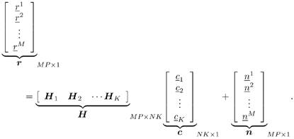


 NK
NK 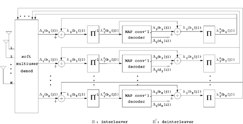


 {+1, -1} denotes the

 [
[ 