| In this lab, you will configure two routers to act as H.323 gateways and one router to act as an H.323 gatekeeper. Routers R1 and R3, which are illustrated in Figure 6-53, will each act as H.323 gateways in different zones. Router R2 will serve as an H.323 gatekeeper and restrict call bandwidth usage between these zones to a total of 64 and limit per-call bandwidth to 16 kbps. Figure 6-53. Lab Topology 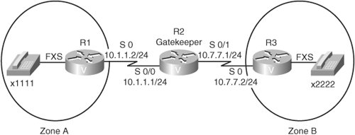
The per-call bandwidth limit of 16 kbps accommodates a single G.729 call. The gatekeeper does not measure the actual bandwidth used per call. Rather, the gatekeeper assumes the required bandwidth for a call is double the bandwidth required for the payload of the call. In this example, a call using the G.729 CODEC requires 8 kbps of bandwidth for the voice payload, not including overhead. Therefore, the H.323 gatekeeper assumes the required bandwidth for the call is double that amount (that is, 16 kbps). Task 1: Configure the H.323 Gatekeeper In this task, you will configure router R2 as an H.323 gatekeeper. Complete these steps: Step 1. | Enable gatekeeper services on router R2 with the gatekeeper command.
| Step 2. | In gatekeeper configuration mode, with the following commands, identify two local zones that are part of the acme.com domain:
zone local ZoneA acme.com 10.7.7.1 zone local ZoneB acme.com Note the IP address of 10.7.7.1 in the first zone local command. This optional parameter specifies the RAS address used when endpoints in local zones register with the gatekeeper. The IOS accepts only a single IP address for the local zone's RAS address, which is why the zone local command for ZoneB does not contain an IP address.
| Step 3. | One of the responsibilities of a gatekeeper is phone number resolution. Therefore, use the following zone prefix commands to indicate which zones can reach which phone numbers:
zone prefix ZoneA 1... zone prefix ZoneB 2... | | | Step 4. | H.323 gateways can register with specific technology prefixes. These technology prefixes can indicate to the gatekeeper what type of calls a gateway can handle. However, if a dial string does not contain a technology prefix, the gateway can use a gateway that has registered with a default technology prefix. In this lab, the H.323 gateways register with a technology prefix of 1#. Therefore, configure the gateway to recognize 1# as a default technology prefix with the gw-type-prefix 1#* default-technology command.
Note Notice the * appended to the technology prefix of 1#. While the H.323 gateways register with a technology prefix of 1#, the H.323 gatekeeper is configured to recognize this technology prefix as 1#*. Think of the * as a wildcard representing the dial string following the technology prefix of 1#. | Step 5. | An H.323 gatekeeper can perform Call Admission Control (CAC) by permitting or rejecting call attempts between zones. In this lab, configure the total amount of voice bandwidth permitted between Zone A and Zone B to 64 kbps, using the bandwidth interzone default 64 command. Next, restrict the bandwidth allowed for a single call to 16 kbps, using the bandwidth session default 16 command.
| Step 6. | A gatekeeper can be administratively shut down, much like you can administratively shut down an interface. Verify that the gatekeeper is administratively up using the no shutdown command.
|
Task 2: Configure H.323 Gateways In this task, you will configure routers R1 and R2 as H.323 gateways that register with the gatekeeper you configured in Task 1. Complete these steps: 1. | Enable H.323 gateway processing on router R1 with the gateway command in global configuration mode.
| 2. | Go into interface configuration mode for the R1 interface that connects R1 to R2 and indicate that the interface is an H.323 interface using the h323-gateway voip interface command.
| 3. | Still in interface configuration mode, tell router R1 to register with the gatekeeper you created in Task 1 using the h323-gateway voip id ZoneA ipaddr 10.7.7.1 1719 command. This command causes router R1 to register as an H.323 gateway in Zone A using the gatekeeper's RAS address of 10.7.7.1 and using the default port number of 1719.
| 4. | Using the h323-gateway voip h323-id R1 command, specify the name router R1 will use when registering with the gatekeeper.
| 5. | Enter the command h323-gateway voip tech-prefix 1# to tell router R1 to register with the gatekeeper using the gatekeeper's default technology prefix of 1#.
| | | 6. | In the lab at the end of Chapter 4, "Voice Dial Peer Configuration," you configured a VoIP dial peer on router R1 that pointed to a phone number of 2222 by sending VoIP packets to an IP address of 10.7.7.2. Enter dial peer configuration mode for this dial peer and remove the previous session target with the no session target ipv4:10.7.7.2 command. Then add a new session target pointing this dial peer to the gatekeeper, using the session target ras command. This command instructs this H.323 gateway to use the RAS channel to send a call setup request to the interface's gatekeeper when attempting to place a call to a dial string of 2222.
| 7. | Now that you have successfully configured router R1, next create a mirrored configuration for router R3. Adapt the commands given in Steps 16 for router R3, such as specifying a zone name of Zone B and an H.323 ID of R3. Also, the VoIP dial peer you modify on router R3 will be the VoIP dial peer that points to a dial string of 1111.
|
Task 3: Verify the Configuration In this task, you will verify the configuration of the H.323 gatekeeper and the two H.323 gateways. Complete these steps: Step 1. | The first indication that your configuration is correct is the ability to successfully place a phone call between extensions 1111 and 2222. Therefore, from extension 1111, attempt to place a phone call to extension 2222. If the call is successful, leave the handsets off-hook while performing the following steps. If, however, the call does not complete successfully, work back through each step of the lab, carefully examining the configurations of the routers.
| Step 2. | With a call successfully in progress, issue the show gateway command on routers R1 and R3 to verify that these gateways have registered with the gatekeeper.
| Step 3. | You can also see what H.323 gateways have registered with the gatekeeper by issuing the show gatekeeper endpoints command from router R2.
| Step 4. | To see the types of RAS messages (for example, admission request [ARQ] and admission confirmation [ACF] messages) sent and received by a gateway, you can issue the show h323 gateway ras command. Issue this command on router R1 and notice the ARQ and the ACF representing the call you were permitted to make.
|
Suggested Solution Although your physical hardware might differ, and your selection of dial peer tags might vary, Examples 6-15 through 6-20 offer possible solutions to the preceding exercise. Example 6-15 shows the configuration for R2's H.323 gatekeeper. Example 6-15. Router R2's H.323 Gatekeeper Configuration gatekeeper zone local ZoneA acme.com 10.7.7.1 zone local ZoneB acme.com zone prefix ZoneA 1... zone prefix ZoneB 2... gw-type-prefix 1#* default-technology arq reject-unknown-prefix bandwidth interzone default 64 bandwidth session default 16 no shutdown
|
Example 6-16 shows the configuration for R1's H.323 gateway. Example 6-16. Router R1's H.323 Gateway Configuration interface Serial0 bandwidth 128 ip address 10.1.1.2 255.255.255.0 encapsulation ppp h323-gateway voip interface h323-gateway voip id ZoneA ipaddr 10.7.7.1 1719 h323-gateway voip h323-id R1 h323-gateway voip tech-prefix 1# ! gateway ! dial-peer voice 2222 voip destination-pattern 2222 session target ras
|
Example 6-17 shows the configuration for R3's H.323 gateway. Example 6-17. Router R3's H.323 Gateway Configuration interface Serial0 bandwidth 2000 ip address 10.7.7.2 255.255.255.0 encapsulation ppp clock rate 2000000 h323-gateway voip interface h323-gateway voip id ZoneB ipaddr 10.7.7.1 1719 h323-gateway voip h323-id R3 interface Serial0 h323-gateway voip tech-prefix 1# ! gateway ! dial-peer voice 1111 voip destination-pattern 1111 session target ras
|
Example 6-18 shows the output of the show gateway command on R1. Example 6-18. Router R1's show gateway Output R1#show gateway H.323 ITU-T Version: 4.0 H323 Stack Version: 0.1 H.323 service is up Gateway R1 is registered to Gatekeeper ZoneA Alias list (CLI configured) E164-ID 1111 H323-ID R1 Alias list (last RCF) E164-ID 1111 H323-ID R1 H323 resource thresholding is Disabled
|
Example 6-19 shows the output of the show gateway command on R3. Example 6-19. Router R3's show gateway Output R3#show gateway H.323 ITU-T Version: 4.0 H323 Stack Version: 0.1 H.323 service is up Gateway R3 is registered to Gatekeeper ZoneB Alias list (CLI configured) E164-ID 2222 H323-ID R3 Alias list (last RCF) E164-ID 2222 H323-ID R3 H323 resource thresholding is Disabled
|
Example 6-20 shows the output of the show gatekeeper endpoints command on R2. Example 6-20. Router R2's show gatekeeper endpoints Output R2#show gatekeeper endpoints GATEKEEPER ENDPOINT REGISTRATION ================================ CallSignalAddr Port RASSignalAddr Port Zone Name Type Flags --------------- ----- -------------- ----- --------- ---- ----- 10.1.1.2 1720 10.1.1.2 52605 ZoneA VOIP-GW E164-ID: 1111 H323-ID: R1 Voice Capacity Max.= Avail.= Current.= 1 10.7.7.2 1720 10.7.7.2 52354 ZoneB VOIP-GW E164-ID: 2222 H323-ID: R3 Voice Capacity Max.= Avail.= Current.= 1 Total number of active registrations = 2
|
Example 6-21 shows the output of the show h323 gateway ras command on R1. Example 6-21. Router R1's show h323 gateway ras Output R1#show h323 gateway ras RAS STATISTICS AT 00:25:56 RAS MESSAGE REQUESTS SENT CONFIRMS RCVD REJECTS RCVD GK Discovery grq 5 gcf 1 grj 0 Registration rrq 34 rcf 34 rrj 0 Admission arq 1 acf 1 arj 0 Bandwidth brq 0 bcf 0 brj 0 Disengage drq 0 dcf 0 drj 0 Unregister urq 0 ucf 0 urj 0 Resource Avail rai 0 rac 0 Req In Progress rip 0
|
|