| This chapter introduced the concept of dial peers. Dial peers provide voice-enabled routers with call-forwarding intelligence. Specifically, a POTS dial peer points to a locally attached device, while a VoIP dial peer points across the network to the IP address of a remote device, such as another voice-enabled router Cisco Unified CallManager. Some circumstances require the manipulation of dialed digits. For example, if a call originally intended to travel across the IP WAN is rerouted across the PSTN, additional digits, such as an area code and an office code, might need to be added to the originally dialed numbers. This chapter explored various methods of manipulating the originally dialed digits. Finally, this chapter considered special purpose connections. These connections included PLAR, PLAR-OPX, trunk, and tie-line connections. Chapter Review Questions The following questions test your knowledge of topics explained in this chapter. You can find the answers to the questions in Appendix A, "Answers to Chapter Review Questions." | Q1: | 1. When an end-to-end call is established, how many inbound call legs are associated with the call? one two three four
| | Q2: | 2. A POTS dial peer performs which of the following two functions? Provides a phone number for the edge network or device Provides a destination address for the edge device that is located across the network Routes the call across the network Identifies the specific voice port that connects the edge network or device Associates the destination address with the next-hop router or destination router, depending on the technology used
| | Q3: | 3. Which command is used to specify the address of the terminating router or gateway? destination-port destination-pattern session target destination address dial-peer terminal
| | | | Q4: | 4. What happens if there is no matching dial peer for an outbound call? The default dial peer is used. Dial peer 0 is used. The POTS dial peer is used. The call is dropped.
| | Q5: | 5. A dial peer is configured with the prefix command. When are digits added to the front of the dial string? Before the outbound dial peer is matched After the outbound dial peer is matched After the digits are sent out of the telephony interface When the digits are received on the dial peer
| | Q6: | 6. Which Cisco IOS command would you use if you wanted a site ID number to be prepended to the dialed digits before they are trunked across the network? connection plar connection plar-opx connection tie-line connection trunk
| | Q7: | 7. What happens when a dial peer is configured with the connection plar command? The caller hears a dial tone, and the number is automatically dialed. The caller does not hear a dial tone, and the call is automatically set up. The caller dials an extension and reaches a telephone at a remote site. The caller does not hear a dial tone, and the call is set up after dialing.
| | Q8: | 8. The voice port at the remote site is configured with this command: voice-port 1/0/0 connection plar 5678 What is the next step in making a call after the user at the remote site lifts the handset? The user must dial extension 5678 to make the call. The telephone will automatically dial 5678, and the user need only dial the extension. The voice port will automatically generate digits 5678 for a dial peer lookup. The voice port has been permanently associated with dial peer 5678, and the call is already established.
| | | | Q9: | 9. How do tie-line connections over IP networks differ from tie-line connections over traditional telephony networks? The calls go over the IP network. Callers can dial a shorter number. Callers at one site can reach callers at any other site. Callers at one site can reach callers at the remote site only.
| | Q10: | 10. On which POTS voice ports must the connection trunk parameter be configured? The voice ports connecting the two FXS trunks The voice ports connecting the FXS trunk to the FXO trunk The voice ports connecting the two PBX trunks The voice ports connecting the E&M trunk to the FXS trunk
|
Lab Exercise: POTS and VoIP Dial Peers In this lab, you will configure four dial peers. Routers R1 and R3, which are illustrated in Figure 4-17, each need a POTS and a VoIP dial peer. The POTS dial peers should point to the locally attached analog phones, and the VoIP dial peers should point to the remote voice gateways. Figure 4-17. Lab Topology 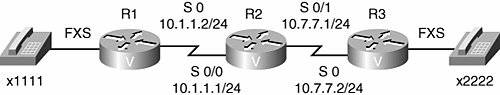
Task 1: Configure POTS Dial Peers In this task, you will configure two POTS dial peers, one on router R1 and one on router R3. Complete these steps: 1. | Create a POTS dial peer on R1 that specifies a destination-pattern of 1111. The port parameter should be configured to match the physical hardware on your router.
| 2. | Create a VoIP dial peer on R1 that specifies a destination-pattern of 2222 and a session target of ipv4:10.7.7.2.
| 3. | Create a POTS dial peer on R3 that specifies a destination-pattern of 2222. The port parameter should be configured to match the physical hardware on your router.
| 4. | Create a VoIP dial peer on R3 that specifies a destination-pattern of 1111 and a session target of ipv4:10.1.1.2.
|
Task 2: Exercise Verification In this task, you will verify the configuration of your POTS and VoIP dial peers. Complete these steps: 1. | To verify the status of your POTS and VoIP dial peers, issue the show dial-peer voice summary command on routers R1 and R3. The ADMIN (that is, administrative) status and the OPER (that is, operational) status should both be "up."
| 2. | At this point, you should be able to place a call between the analog phones. Take extension 1111 (that is, the analog phone attached to router R1) off hook and dial 2222. The analog phone attached to router R3 should ring. Take the other analog phone (that is, the analog phone attached to router R3) off hook. You should now have a bidirectional conversation.
| 3. | Repeat Step 2, but initiate the phone call from extension 2222 and call extension 1111.
|
Suggested Solution Although your physical hardware might differ, and your selection of dial peer tags might vary, Example 4-23 and Example 4-24 offer one solution to the preceding exercise. Example 4-23. Router R1's Configuration R1#configure terminal R1(config)#dial-peer voice 1111 pots R1(config-dial-peer)#destination-pattern 1111 R1(config-dial-peer)#port 1/1 R1(config-dial-peer)#exit R1(config)#dial-peer voice 2222 voip R1(config-dial-peer)#destination-pattern 2222 R1(config-dial-peer)#session target ipv4:10.7.7.2
|
Example 4-24. Router R3's Configuration R1#configure terminal R1(config)#dial-peer voice 2222 pots R1(config-dial-peer)#destination-pattern 2222 R1(config-dial-peer)#port 1/1 R1(config-dial-peer)#exit R1(config)#dial-peer voice 1111 voip R1(config-dial-peer)#destination-pattern 1111 R1(config-dial-peer)#session target ipv4:10.1.1.2
|
The show dial-peer voice summary results for routers R1 and R3, using the preceding suggested solution, are shown in Example 4-25 and Example 4-26. Example 4-25. Router R1's show dial-peer voice summary Result R1#show dial-peer voice summary dial-peer hunt 0 AD PRE PASS OUT TAG TYPE MIN OPER PREFIX DEST-PATTERN FER THRU SESS-TARGET STAT PORT 1111 pots up up 1111 0 up 1/1 2222 voip up up 2222 0 syst ipv4:10.7.7.2
|
Example 4-26. Router R3's show dial-peer voice summary Result R3#show dial-peer voice summary dial-peer hunt 0 AD PRE PASS OUT TAG TYPE MIN OPER PREFIX DEST-PATTERN FER THRU SESS-TARGET STAT PORT 2222 pots up up 2222 0 up 1/1 1111 voip up up 1111 0 syst ipv4:10.1.1.2
|
Lab Exercise: PLAR Connection In this lab, you will configure the FXS voice port on router R1 for PLAR. The PLAR configuration will cause router R1 to dial extension 2222 when extension 1111 goes off hook, as shown earlier in the topology depicted in Figure 4-17. Task 1: Configure PLAR In this task, you will configure PLAR on router R1's FXS port. Complete these steps: 1. | Enter voice port configuration mode for the FXS port on router R1.
| | | 2. | Configure the voice port to automatically dial extension 2222 whenever the phone attached to the voice port goes off hook, by issuing the connection plar 2222 command.
|
Task 2: Exercise Verification In this task, you will verify router R1's PLAR configuration. Complete these steps: 1. | Issue the show voice port command for the FXS port on your R1 router. Note the Connection Mode in the output, which should be PLAR.
| 2. | To verify the proper operation of PLAR, take router R1's analog phone off hook. The analog phone attached to router R3 should then ring.
|
Suggested Solution Although your physical hardware might differ, Example 4-27 offers one solution to the preceding exercise. Example 4-27. Router R1's PLAR Configuration R1#configure terminal R1(config)#voice-port 1/1 R1(config-voiceport)#connection plar 2222
|
The show voice port 1/1 command on router R1 yields the output shown in Example 4-28. Note that the connection mode is PLAR. Example 4-28. Router R1's show voice port 1/1 Output R1#show voice port 1/1 FXS 1/1 Slot is 1, Port is 1 Type of VoicePort is FXS Operation State is DORMANT Administrative State is UP No Interface Down Failure Description is not set Noise Regeneration is enabled Non Linear Processing is enabled Non Linear Mute is disabled Non Linear Threshold is -21 dB Music On Hold Threshold is Set to -38 dBm In Gain is Set to 0 dB Out Attenuation is Set to 0 dB Echo Cancellation is enabled Echo Cancellation NLP mute is disabled Echo Cancellation NLP threshold is -21 dB Echo Cancel Coverage is set to 64 ms Echo Cancel worst case ERL is set to 6 dB Playout-delay Mode is set to adaptive Playout-delay Nominal is set to 60 ms Playout-delay Maximum is set to 200 ms Playout-delay Minimum mode is set to default, value 40 ms Playout-delay Fax is set to 300 ms Connection Mode is plar Connection Number is 2222 Initial Time Out is set to 10 s Interdigit Time Out is set to 10 s Call Disconnect Time Out is set to 60 s Supervisory Disconnect Time Out is set to 750 ms Ringing Time Out is set to 180 s Wait Release Time Out is set to 30 s Companding Type is u-law Coder Type is g729ar8 Voice Activity Detection is enabled Nominal Playout Delay is 60 milliseconds Maximum Playout Delay is 200 milliseconds Region Tone is set for US Analog Info Follows: Currently processing none Maintenance Mode Set to None (not in mtc mode) Number of signaling protocol errors are 0 Impedance is set to 600r Ohm Analog interface A-D gain offset = -3.0 dB Analog interface D-A gain offset = -3.0 dB FXS idle voltage set to low Station name None, Station number None Translation profile (Incoming): Translation profile (Outgoing): Voice card specific Info Follows: Signal Type is loopStart Ring Frequency is 20 Hz Hook Status is On Hook Ring Active Status is inactive Ring Ground Status is inactive Tip Ground Status is active Digit Duration Timing is set to 100 ms InterDigit Duration Timing is set to 100 ms Hookflash-in Timing is set to 1000 ms Hookflash-out Timing is set to 400 ms No disconnect acknowledge Ring Cadence is defined by CPTone Selection Ring Cadence are [20 40] * 100 msec Ringer Equivalence Number is set to 1 InterDigit Pulse Duration Timing is set to 500 msdial-peer hunt 0
|
|