Configuring Dial Peers
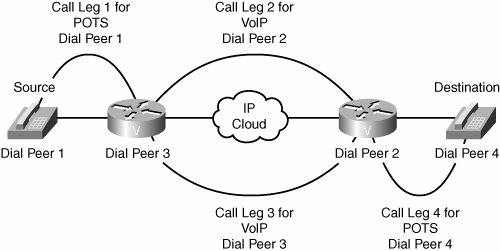
| As a call is set up across the network, the existence of various parameters is checked and negotiated. A mismatch in parameters can cause call failure. Therefore, it is important to understand how routers interpret call legs and how call legs relate to inbound and outbound dial peers. Successful implementation of a VoIP network relies heavily on the proper application of dial peers, the digits they match, and the services they specify. A network designer needs in-depth knowledge of dial peer configuration options and their uses. This section discusses the proper use of digit manipulation and the configuration of dial peers. Understanding Call LegsCall legs are logical connections between any two telephony devices, such as gateways, routers, Cisco Unified CallManagers, or telephony endpoint devices. Additionally, call legs are routercentric. When an inbound call arrives, it is processed separately until the destination is determined. Then a second outbound call leg is established, and the inbound call leg is switched to the outbound voice port. The topology shown in Figure 4-1 illustrates the four call legs involved in an endtoend call between two voiceenabled routers. Figure 4-1. Call Legs An endtoend call consists of four call legs: two from the source router's perspective and two from the destination router's perspective. To complete an endtoend call from either side and send voice packets back and forth, you must configure all four dial peers. Dial peers are only used to set up calls. After the call is established, dial peers are no longer employed. An inbound call leg occurs when an incoming call comes into the router or gateway. An outbound call leg occurs when a call is placed from the router or gateway, as depicted in Figure 4-2. Figure 4-2. End-to-End Calls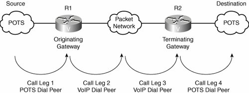 A call is segmented into call legs, and a dial peer is associated with each call leg. The process for call setup, as diagramed in Figure 4-2, is:
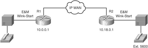
Understanding Dial PeersWhen a call is placed, an edge device generates dialed digits as a way of signaling where the call should terminate. When these digits enter a router voice port, the router must decide whether the call can be routed and where the call can be sent. The router does this by searching a list of dial peers. A dial peer is an addressable call endpoint. The address is called a destination pattern and is configured in every dial peer. Destination patterns use both explicit digits and wildcard variables to define one telephone number or range of numbers. Dial peers define the parameters for the calls that they match. For example, if a call is originating and terminating at the same site and is not crossing through slow-speed WAN links, then the call can cross the local network uncompressed and without special priority. A call that originates locally and crosses the WAN link to a remote site may require compression with a specific coder-decoder (CODEC). In addition, this call may require that voice activity detection (VAD) be turned on and will need to receive preferential treatment by specifying a higher priority level. Cisco voice-enabled routers support four types of dial peers, including POTS, VoIP, VoFR, and VoATM. However, this book focuses on POTS and VoIP dial peers:
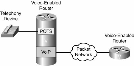
In Figure 4-3, the telephony device connects to the Cisco voice-enabled router. The POTS dial peer configuration includes the telephone number of the telephony device and the voice port to which it is attached. The router determines where to forward incoming calls for that telephone number. Figure 4-3. Dial Peers The Cisco voiceenabled router VoIP dial peer is connected to the packet network. The VoIP dial peer configuration includes the destination telephone number (or range of numbers) and the next-hop or destination voiceenabled router network address. Follow these steps to enable a router to complete a VoIP call:
Configuring POTS Dial PeersBefore the configuration of Cisco IOS dial peers can begin, you must have a good understanding of where the edge devices reside, what type of connections need to be made between these devices, and what telephone numbering scheme is applied to the devices. Follow these steps to configure POTS dial peers:
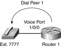
The dial peer type will be specified as POTS because the edge device is directly connected to a voice port, and the signaling must be sent from this port to reach the device. There are two basic parameters that need to be specified for the device: the telephone number and the voice port. When a PBX is connecting to the voice port, a range of telephone numbers can be specified. Figure 4-4 shows POTS dial peers. Example 4-1 illustrates proper POTS dial peer configuration on the Cisco voice-enabled router shown in Figure 4-4. The dialpeer voice 1 pots command notifies the router that dial peer 1 is a POTS dial peer with a tag of 1. The tag is a number that is locally significant to the router. Although the tag does not need to match the phone number specified by the destination-pattern command, many administrators recommend configuring a tag that does match a dial-peer's phone number, to help make the configuration more intuitive. The destination-pattern 7777 command notifies the router that the attached telephony device terminates calls destined for telephone number 7777. The port 1/0/0 command notifies the router that the telephony device is plugged into module 1, voice interface card (VIC) slot 0, and voice port 0. Figure 4-4. POTS Dial Peers Example 4-1. Configuration for Dial Peer 1 on Router 1
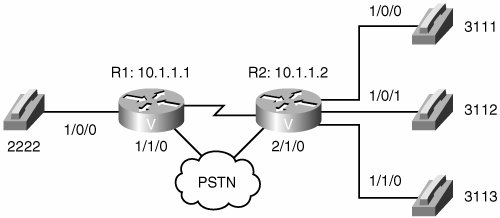
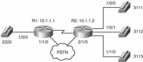
Practice Scenario 1: POTS Dial Peer ConfigurationThroughout this chapter, you will practice what you have learned. In this scenario, assume that there is a data center at the R1 site and executive offices at the R2 site. Using the diagram shown in Figure 4-5, create POTS dial peers for the four telephones shown. Notice that three configuration commands are required for R1, and nine configuration commands are required for R2. You might want to use a separate sheet of paper to write your configuration commands. Figure 4-5. POTS Dial Peer Configuration R1: __________________________________________________________________________________ __________________________________________________________________________________ __________________________________________________________________________________ R2: ______________________________________________________________________________ __________________________________________________________________________________ __________________________________________________________________________________ __________________________________________________________________________________ R2: __________________________________________________________________________________ __________________________________________________________________________________ __________________________________________________________________________________ __________________________________________________________________________________ __________________________________________________________________________________ Practice Scenario 1: Suggested SolutionAlthough your choice of dial peer tags might vary, the following offers a suggested solution to Practice Scenario 1: R1: dial-peer voice 2222 pots destination-pattern 2222 port 1/0/0 R2: dial-peer voice 3111 pots destination-pattern 3111 port 1/0/0 dial-peer voice 3112 pots destination-pattern 3112 port 1/0/1 dial-peer voice 3113 pots destination-pattern 3113 port 1/1/0 Configuring VoIP Dial PeersThe administrator must know how to identify the far-end voice-enabled device that will terminate the call. In a small network environment, the device might be the IP address of the remote device. In a large environment, identifying the device might mean pointing to a Cisco Unified CallManager or gatekeeper for address resolution and call admission control (CAC) to complete the call. Follow these steps to configure VoIP dial peers:
The dial peer specified as a VoIP dial peer alerts the router that it must process a call according to the various dial peer parameters. The dial peer must then send the call setup information in IP packets for transport across the network. Specified parameters might include the CODEC used for compression (for example, VAD) or marking the packet for priority service. The destinationpattern parameter configured for this dial peer is typically a range of numbers that are reachable via the remote router or gateway. Because this dial peer points to a device across the network, the router needs a destination IP address to put in the IP packet. The session target parameter allows the administrator to specify either an IP address of the terminating router or gateway or another device. For example, a gatekeeper or Cisco Unified CallManager might return an IP address of that remote terminating device. To determine which IP address a dial peer should point to, Cisco recommends you use a loopback address. The loopback address is always up on a router as long as the router is powered on and the interface is not administratively shut down. The reason an interface IP address is not recommended is that if the interface goes down the call will fail, even if there is an alternate path to the router. Figure 4-6 shows VoIP dial peers. Example 4-2 lists the proper VoIP dial peer configuration on Router 1, which is a Cisco voiceenabled router shown in Figure 4-6. The dialpeer voice 2 voip command notifies the router that dial peer 2 is a VoIP dial peer with a tag of 2. The destinationpattern 8888 command notifies the router that this dial peer defines an IP voice path across the network for telephone number 8888. The session target ipv4:10.18.0.1 command defines the IP address of the router that is connected to the remote telephony device. Figure 4-6. VoIP Dial Peers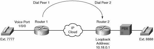 Example 4-2. Configuration for Dial Peer 2 on Router 1
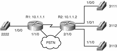
Practice Scenario 2: VoIP Dial Peer ConfigurationCreate VoIP dial peers for each of the R1 and R2 sites based on the diagram presented in Figure 4-7. Figure 4-7. VoIP Dial Peer Configuration R1: __________________________________________________________________________________ __________________________________________________________________________________ __________________________________________________________________________________ __________________________________________________________________________________ __________________________________________________________________________________ __________________________________________________________________________________ __________________________________________________________________________________ __________________________________________________________________________________ __________________________________________________________________________________ R2: __________________________________________________________________________________ __________________________________________________________________________________ _________________________________________________________________________________ Practice Scenario 2: Suggested SolutionAlthough your choice of dial peer tags might vary, the following offers a suggested solution to Practice Scenario 2: R1: dial-peer voice 3111 voip destinationpattern 3111 session target ipv4:10.1.1.2 dial-peer voice 3112 voip destinationpattern 3112 session target ipv4:10.1.1.2 dial-peer voice 3113 voip destinationpattern 3113 session target ipv4:10.1.1.2 R2: dial-peer voice 2222 voip destination-pattern 2222 session target ipv4:10.1.1.1 The next section of this chapter introduces you to the use of wildcards to minimize the number of dial peers you must configure. Configuring destination-pattern OptionsAs previously discussed, the destination pattern associates a telephone number with a given dial peer. It also determines the dialed digits that the router collects and forwards to the remote telephony interface, such as a PBX, Cisco Unified CallManager, or PSTN. You must configure a destination pattern for each POTS and VoIP dial peer that you define on the router. The destination pattern can indicate a complete telephone number or a partial telephone number with wildcard digits, or it can point to a range of numbers defined in a variety of ways. Destinationpattern options include the following:
When the calling party finishes entering dialed digits, there is a pause equal to the interdigit timeout value before the router processes the call. The calling party can immediately terminate the interdigit timeout by entering the pound character (#), which is the default termination character. Because the default interdigit timer is set to 10 seconds, users might experience a long call setup delay. Note Cisco IOS software does not check the validity of the E.164 telephone number. It accepts any series of digits as a valid number. Table 4-1 demonstrates the use of various destination pattern wildcards, including the period, brackets, and the ".T."
Characteristics of the Default Dial PeerWhen a matching inbound dial peer is not found, the router resorts to a virtual dial peer called the default dial peer. The default dial peer is often referred to as dial peer 0. Note Default dial peers are used for inbound matches only. They are not used to match outbound calls that do not have a dial peer configured. Dial peer 0 for inbound VoIP peers has the following characteristics:
For inbound POTS peers, dial peer 0 has no IVR application. You cannot change the default configuration for dial peer 0. Default dial peer 0 fails to negotiate nondefault capabilities or services. When the default dial peer is matched on a VoIP call, the call leg that is set up in the inbound direction uses any supported CODEC for voice compression that is based on the requested CODEC capability coming from the source router. When a default dial peer is matched, the voice path in one direction may have different parameters than the voice path in the return direction. This might cause one side of the connection to report good quality voice while the other side reports poor quality voice. For example, the outbound dial peer has VAD disabled, but the inbound call leg is matched against the default dial peer, which has VAD enabled. VAD would be on in one direction and off in the return direction. When the default dial peer is matched on an inbound POTS call leg, there is no default IVR application with the port. As a result, the user gets a dial tone and proceeds with dialed digits. Interestingly, the default dial peer cannot be viewed using show commands. In Figure 4-8, only oneway dialing is configured. Example 4-3 and Example 4-4 illustrate the configuration for this topology. The caller at extension 7777 can call extension 8888 because there is a VoIP dial peer configured on Router 1 to route the call across the network. However, there is no VoIP dial peer configured on Router 2 to point calls across the network toward Router 1. Therefore, there is no dial peer on Router 2 that will match the calling number of extension 7777 on the inbound call leg. If no incoming dial peer matches the calling number, the inbound call leg automatically matches to a default dial peer (POTS or VoIP). Figure 4-8. Default Dial Peer 0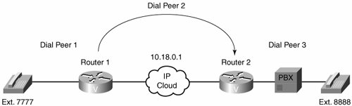 Example 4-3. Router 1 Configuration
Example 4-4. Router 2 Configuration
Matching Inbound Dial PeersWhen determining how inbound dial peers are matched on a router, it is important to note whether the inbound call leg is matched to a POTS or VoIP dial peer. Matching occurs in the following manner:
Three information elements sent in the call setup message are matched against four configurable dialpeer command attributes. Table 4-2 describes the three call setup information elements.
The four configurable dial peer command attributes are detailed in Table 4-3.
When the Cisco IOS router or gateway receives a call setup request, it looks for a dial peer match for the incoming call. This is not digit-by-digit matching. Instead, the router uses the full digit string received in the setup request for matching against the configured dial peers. The router or gateway matches call setup element parameters in the following order:
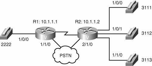
Because call setups always include DNIS information, it is recommended that you use the incoming called-number command for inbound dial peer matching. Configuring incoming called-number is useful for a company that has a central call center providing support for a number of different products. Purchasers of each product get a unique tollfree number to call for support. All support calls are routed to the same trunk group destined for the call center. When a call comes in, the computer telephony system uses the DNIS to flash the appropriate message on the computer screen of the agent to whom the call is routed. The agent will then know how to customize the greeting when answering the call. The calling number ANI with answer-address is useful when you want to match calls based on the originating calling number. For example, when a company has international customers who require foreign-language-speaking agents to answer the call, the call can be routed to the appropriate agent based on the country of call origin. You must use the calling number ANI with destination-pattern when the dial peers are set up for two-way calling. In a corporate environment, the head office and remote sites must be connected. As long as each site has a VoIP dial peer configured to point to each site, inbound calls from each remote site will match against that dial peer. Practice Scenario 3: Matching Inbound Dial PeersIn this practice scenario, assume that you are setting up a technical support center for desktop PCs, printers, and laptops. Customers who dial specific numbers need to reach the appropriate technical support staff. Using the diagram in Figure 4-9, create dial peers on R1 to route incoming calls (that is, from the PSTN) by the incoming called number to the appropriate site. Because the focus of this practice scenario is dial peer configuration, as opposed to digit manipulation, assume the DNIS has already been truncated to four digits. Figure 4-9. Matching Inbound Dial Peers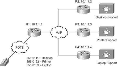 R1: __________________________________________________________________________________ __________________________________________________________________________________ __________________________________________________________________________________ __________________________________________________________________________________ __________________________________________________________________________________ __________________________________________________________________________________ __________________________________________________________________________________ __________________________________________________________________________________ __________________________________________________________________________________ Practice Scenario 3: Suggested SolutionAlthough your choice of dial peer tags might vary, the following offers a suggested solution to Practice Scenario 3: R1: dialpeer voice 111 voip incoming callednumber 5550111 session target ipv4:10.1.1.2 dial-peer voice 122 voip incoming callednumber 5550122 session target ipv4:10.1.1.3 dial-peer voice 133 voip incoming callednumber 5550133 session target ipv4:10.1.1.4 Matching Outbound Dial PeersOutbound dial peer matching is completed on a digit-by-digit basis. Therefore, the router or gateway checks for dial peer matches after receiving each digit and then routes the call when a full match is made. The router or gateway matches outbound dial peers in the following order:
In Example 4-5, dial peer 1 matches any digit string that does not match the other dial peers more specifically. Dial peer 2 matches any seven-digit number in the 30 and 40 range of numbers starting with 55501. Dial peer 3 matches any sevendigit number in the 20 range of numbers starting with 55501. Dial peer 4 matches the specific number 5550124 only. When the number 5550124 is dialed, dial peers 1, 3, and 4 all match that number, but dial peer 4 places that call because it contains the most specific destination pattern. Example 4-5. Matching Outbound Dial Peers
Configuring Hunt GroupsCisco voiceenabled routers support the concept of hunt groups, sometimes called rotary groups, in which multiple dial peers are configured with the same destination pattern. The destination of each POTS dial peer is a single voice port to a telephony interface so hunt groups help ensure that calls get through even when a specific voice port is busy. If the router is configured to hunt, it can forward a call to another voice port that is not busy. The following is a listing of hunt group commands:
In some business environments, such as call centers or sales departments, there may be a group of agents available to answer calls coming in to a single number. Scenario 1 may randomly distribute the calls between all agents. Scenario 2 may send calls to the senior agents first and to the junior agents only when all senior agents are busy. Both of these scenarios can be serviced by configuring a hunt group with specific commands to control the hunt actions. Follow these steps to configure hunt groups:
You must use the dial-peer hunt global configuration command to change the default selection order of the procedure or to choose different methods for hunting through dial peers. To view the current setting for dial-peer hunt, use the show dial-peer voice summary command. If you do not want to hunt through a range of dial peers, the huntstop command disables dial peer hunting. After you enter this command, no further hunting is allowed if a call fails on the selected dial peer. This is useful in situations where it is undesirable to hunt to a less-specific dial peer if the more specific dial peer fails. For example, if a call is destined for a particular staff member and the person is on the phone, the router searches for any other dial peer that might match the dialed number. If there is a more generic destination pattern in another dial peer that also matches, the call is routed to the more generic destination pattern. Configuring the huntstop command in the more specific dial peer will send the caller a busy signal and stop hunting. You can mix POTS and VoIP dial peers when creating hunt groups. This is useful if you want incoming calls sent over the IP network but network connectivity fails. You can then reroute the calls back through the PBX, or through the router, to the PSTN. By default, the router selects dial peers in a hunt group according to the following criteria, in the order listed:
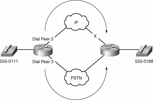
The destination pattern that matches the greatest number of dialed digits is the first dial peer selected by the router. For example, if one dial peer is configured with a dial string of 345.... and a second dial peer is configured with 3456789, the router selects 3456789 first because it has the longest explicit match of the two dial peers. Without a PBX, if the line is currently in use, the desired action is to send a call to a voice-mail system or a receptionist, instead of giving the caller a busy signal. If the destination pattern is the same for several dial peers, you can configure the priority by using the preference dial peer command. This would be the configuration for scenario 2, where the dial peers connecting to the senior agents would have preference 0 and the dial peers connecting to the junior agents would have preference 1. The lower the preference is set, the more likely that dial peer will handle the call. By default, if all destination patterns are equal, the preference is set to 0 on all dial peers. If the preference does not act as the tiebreaker, then a dial peer matching the called number will be picked randomly. Example 4-6 shows an example of configuring a hunt group to send calls to the PSTN if the IP network fails, as shown in Figure 4-10. For all calls going to 555-0188, VoIP dial peer 2 is matched first because the preference is set to 0. If the path through the IP network fails, POTS dial peer 3 is matched and the call is forwarded through the PSTN. The forwarddigits command forwards all digits to the PSTN to automatically complete the call without a secondary dial tone. Example 4-6. HuntGroup Configuration
Figure 4-10. PSTN Fallback Using a Hunt Group Practice Scenario 4: Configuring Hunt GroupsConsider the diagram presented in Figure 4-11. Create a hunt group using the preference command on R2. Configure it so that if extension 3111 is busy, the call rings extension 3112. Assume that you have POTS dial peers for all three extensions already configured. Figure 4-11. Configuring Hunt Groups R2: Already configured dialpeer voice 1 pots destinationpattern 3111 port 1/0/0 ! dialpeer voice 2 pots destinationpattern 3112 port 1/0/1 ! dialpeer voice 3 pots destinationpattern 3113 port 1/1/0 R2: Hunt group dial peer __________________________________________________________________________________ __________________________________________________________________________________ __________________________________________________________________________________ __________________________________________________________________________________ Practice Scenario 4: Suggested SolutionAlthough your choice of a dial peer tag and priority value might vary, the following offers a suggested solution to Practice Scenario 4: R2: dial-peer voice 4 pots destination-pattern 3111 port 1/0/1 preference 1 Collecting and Analyzing DigitsEffective destination-pattern design requires an understanding of how a voice-enabled router collects and analyzes digits. By default, when the terminating router matches a dial string to an outbound POTS dial peer, the router strips off the left-justified digits that explicitly match the destination pattern. The remaining wildcard digits are forwarded to the telephony interface, which connects devices such as a PBX or the PSTN. Use the no digitstrip command to disable the automatic digit-stripping function. This allows the router to match digits and pass them to the telephony interface. However, digit stripping is the desired action in some situations. There is no need to forward digits out of a POTS dial peer if it is pointing to a Foreign Exchange Station(FXS) port that connects a telephone or fax machine. When digit stripping is turned off on this type of port, the user will hear tones after answering the call because any unconsumed and unmatched digits are passed through the voice path after the call is answered. When a PBX or the PSTN is connected through the POTS dial peer, digit stripping is not desired because these devices need additional digits to further direct the call. In these situations, the administrator must assess the number of digits that need to be forwarded for the remote device to correctly process the call. With a VoIP dial peer, all digits are passed across the network to the terminating voice-enabled router. When a voice call enters the network, the router collects digits as follows:
Example 4-7 and Example 4-8 demonstrate the impact that overlapping destination patterns have on the call routing decision. In Example 4-7, the destination pattern in dial peer 1 is a subset of the destination pattern in dial peer 2. The router matches one digit at a time against available dial peers. This means that an exact match will always occur on dial peer 1, and dial peer 2 will never be matched. Only the collected digits of 555 will be forwarded. Example 4-7. Dial Peer Digit Consumption with VariableLength Destination Patterns
In Example 4-8, the length of the destination patterns in both dial peers is the same. Dial peer 2 has a more specific value than dial peer 1, so it will be matched first. If the path to IP address 10.18.0.2 is unavailable, dial peer 1 will be used when 5550124 is dialed. Collected digits of 5550124 will be forwarded. Example 4-8. Dial Peer Digit Consumption with Fixed-Length Digit Consumption
Destination patterns are matched based on the longest explicit number match. Digits collected are dependant on the configured destination pattern. Table 4-5 describes how different number combinations are matched and collected.
In the first row of Table 4-5, the destination pattern specifies a seven-digit string. The first digit must be a five, and the remaining six digits can be any valid digits. All seven digits must be entered before the destination pattern is matched. In the second row, the destination pattern specifies a seven-digit string. The first three digits must be 555, and the remaining four digits can be any valid digits. All seven digits must be entered before the destination pattern is matched. In the third row, the destination pattern specifies a three-digit string. The dialed digits must be exactly 555. When the user begins to dial the seven-digit number, the destination pattern matches after the first three digits are entered. The router then stops collecting digits and places the call. If the call is set up quickly, the answering party at the other end may hear the remaining four digits as the user finishes dialing the string, because after a call is set up, any dual-tone multifrequency (DTMF) tones are sent through the voice path and played out at the other end. In the last row, the destination pattern specifies a variable-length digit string that is at least three digits long. The first three digits must be exactly 555, and the remaining digits can be any valid digits. The "T" tells the router to continue collecting digits until the interdigit timer expires. The router stops collecting digits when the timer expires or when the user presses the pound (#) key. Manipulating DigitsDigit manipulation is the task of adding or subtracting digits from the original dialed number to accommodate user dialing habits or gateway needs. The digits can be manipulated before matching an inbound or outbound dial peer. The following list describes digit manipulation commands issued in dial peer configuration mode:
Note You can use the show num-exp command to view the configured number-expansion table. You can use the show dialplan number number command to confirm the presence of a valid dial peer to match the newly expanded number.
You can also use translation rules to change the numbering type for a call. For example, some gateways may tag a number with more than 11 digits as an international number, even when the user must dial 9 to reach an outside line. In this case, the number that is tagged as an international number needs to be translated into a national number, without the 9, before it is sent to the PSTN. As illustrated in this section, there are numerous ways to manipulate digits at various stages of call completion. The administrator needs to determine which command will be most suitable and the requirements that are necessary for manipulation. Note To test configured translation rules, you can use the test translation command. Example 4-9 shows a sample configuration using the prefix command. Example 4-9. The prefix Command
In the sample configuration using the prefix command, the device attached to port 1/0/0 needs all seven digits to process the call. On a POTS dial peer, only wildcard-matched digits are forwarded by default. Use the prefix command to send the prefix numbers 555 before forwarding the four wildcard-matched digits. Example 4-10 illustrates a sample configuration using the forward-digits command. Example 4-10. The forward-digits Command
In the sample configuration using the forward-digits command, the device attached to port 1/0/0 needs all seven digits to process the call. On a POTS dial peer, only wildcard-matched digits are forwarded by default. The forward-digits command allows the user to specify the total number of digits to forward. Example 4-11 provides a sample configuration using the number expansion table (num-exp)command. Example 4-11. The num-exp Command
In the sample configuration using the num-exp command, the extension number 2... is expanded to 5552... before an outbound dial peer is matched. For example, the user dials 2401, but the outbound dial peer 1 is configured to match 5552401. Example 4-12 presents a sample configuration using the translation-rule command. Example 4-12. The translation-rule Command
In the sample configuration using the translation-rule command, the rule is defined to translate 2401 into 5552401. The dial peer translate-outgoing called-number 5 command notifies the router to use the globally defined translation rule 5 to translate the number before sending the string out the port. The translation rule is applied as an outbound translation from the POTS dial peer. Example 4-13 demonstrates a translation rule that converts any called number that starts with 91 and is tagged as an international number into a national number without the 9 before sending it to the PSTN. Example 4-13. Sample translation-rule Configuration
The IOS can also leverage regular expression characters, as shown in Table 4-6, to create powerful translation rules.
Example 4-14 offers an example of a translation rule using regular expressions. Example 4-14. Sample translation-rule Using Regular Expressions
To interpret rule 1, consider the following:
Rule 2 is functionally equivalent to rule 1. The matching pattern in rule 2 is divided into two sets. The first set is 555 and the second set is the four digits following the 555. The replacement pattern starts with 444 and then appends the \2, which adds the second set from the matching pattern. For illustrative purposes, Table 4-7 shows several examples of translation rule regular expressions.
Practice Scenario 5: Digit ManipulationAssume that all POTS and VoIP dial peers are configured for the topology illustrated in Figure 4-12. Create a dial peer to divert calls from R1 to R2 across the PSTN in the event of failure of the VoIP network. Assume that digits must be forwarded to the PSTN, and a prefix of 555 is necessary. Figure 4-12. Digit Manipulation R1: _______________________________________________________________________________ _______________________________________________________________________________ _______________________________________________________________________________ _______________________________________________________________________________ _______________________________________________________________________________ Practice Scenario 5: Suggested SolutionAlthough your choice of a dial peer tag might vary, the following offers a suggested solution to Practice Scenario 5: R1: dial-peer voice 5 pots destination-pattern 311[1-3] port 1/1/0 prefix 555311 preference 1 Special-Purpose ConnectionsIntegrating VoIP technologies with legacy PBXs and the public switched telephone network (PSTN) often requires voice port configuration for certain connection types. The original design of a PBX might have called for tie-lines between PBXs. When replacing tie-lines with a VoIP solution, special configuration at the voice port level can emulate the original tie-line design. In many cases, telecommuters require access to PBX services that resemble other extensions of the PBX, regardless of where the telecommuters actually reside. In other instances, telephones, such as lobby customer-service telephones, need to be connected directly to customer-service staff. You can configure voice ports to support special connection requirements. These requirements usually reflect the needs of a specific business environment that must connect to the network in a special way. The following list describes the available connection types and their application:
Table 4-8 illustrates the use of the connection command to establish these special purpose connections.
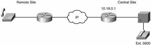
The next sections describe each connection type in more detail. PLARWith a PLAR connection, when the calling telephone goes off hook, a predefined network dial peer is automatically matched, which sets up a call to the destination telephone or PBX. Callers do not hear a dial tone nor do they have to dial a number. PLAR connections are widely used in the business world. One common use is to connect stockbrokers with trading floors. Timing is critical when dealing with stock transactions; the amount of time it takes to dial a number and get a connection can be costly in some cases. Another common use is in the travel sector, directly connecting travelers with services. Often, at places like airports, the traveler will see display boards advertising taxi companies, car rental companies, and local hotels. These displays often have telephones that connect the traveler directly with the service of choice. The device is preconfigured with the telephone number of the desired service. One obvious difference between these telephones and a normal telephone is that they lack a dial mechanism. Figure 4-13 shows a PLAR topology whose syntax is provided in Example 4-15 and Example 4-16. Figure 4-13. PLAR Connection Example 4-15. Remote Site Router Configuration
Example 4-16. Central Site Router Configuration
The following actions occur during the establishment of the PLAR connection illustrated in Figure 4-13:
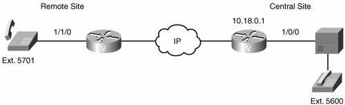
PLAR-OPXWith a PLAR-OPX connection, company staff can dial an extension and reach the remote telephone as though it were on site. The remote telephone has access to PBX services such as voice mail and extension dialing. This functionality is most often used when on-site staff become telecommuters. Many companies are cutting back on office space in expensive locations and are setting up their staff with home offices. A PLAR-OPX connection is configured between the office and the remote site so that a telecommuter can continue to access all the corporate telephony services in the same manner as before. This approach allows a telecommuter to dial the same extensions to reach other staff and to have access to long-distance dialing and other voice services via the same calling codes. From the office perspective, on-site staff can reach the telecommuter by dialing the same extension as before. One OPX connection feature is that when a call is being attempted the voice-enabled router or gateway that takes the call from the PBX or Cisco Unified CallManager will not report a call completion until the far end has answered the call. Without the OPX configuration, the PBX or Cisco Unified CallManager passes the call to the local gateway or router. Then the gateway or router routes the call to the PSTN. After the PSTN sends ringing current to the telephone, the router reports call completion back to the PBX or Cisco Unified CallManager. At this point, the call is completed. The problem is that if the call is not answered, there is no way to reroute the call to the corporate voice mail server. From the PBX or Cisco Unified CallManager perspective, the call is completed. When you configure the OPX, however, the gateway or router will not report call completion until the telephone is actually answered. Figure 4-14 illustrates a PLAR-OPX topology whose syntax is provided in Example 4-17 and Example 4-18. Figure 4-14. PLAR-OPX Connection Example 4-17. Remote Site Router Configuration
Example 4-18. Central Site Router Configuration
Trunk ConnectionA trunk connection remains permanent in the absence of active calls and is established immediately after configuration. The ports on either end of the connection are dedicated until you disable trunking for that connection. If, for some reason, the link between the two voice ports goes down, the virtual trunk reestablishes itself after the link comes back up. This trunk configuration is useful when a permanent connection is desired between two devices. For example, a caller at one end of the trunk connection can pick up the telephone and speak into it without dialing any digits or waiting for call setup. This is analogous to the red telephone to the Kremlin that is depicted in vintage movies. With a trunk connection, there is no digit manipulation performed by the gateway or router. Because this is a permanent connection, digit manipulation is not necessary. Figure 4-15 shows the establishment of a trunk connection. The syntax for the topology is provided in Examples 4-19 and 4-20. Example 4-19. Router R1's Configuration
Figure 4-15. Trunk Connection The syntax for the topology shown in Figure 4-15 is provided in Example 4-19 and Example 4-20. Example 4-20. Router R2's Configuration
In Example 4-19, router R1 is configured to set up a trunk connection from voice port 1/0:1 to a remote voice-enabled router with the IP address of 10.18.0.1 (router R2). This is done by specifying the same number in the connection trunk voice port command as in the appropriate dial peer destination-pattern command. In this example, router R1 uses connection trunk 55, which matches VoIP dial peer 55. The call is routed to router R2, which matches the 55 in a POTS dial peer. Router R2 is also configured to set up a trunk connection from its voice port, 1/0:5, to a remote voice-enabled router with the IP address of 10.0.0.1 (router R1). Router R2 uses 44 as its connection trunk number. These trunk connections are set up when the routers power on and remain up until a router is powered down or the ports are shut down. The following conditions must be met for a VoIP network to support virtual trunk connections:
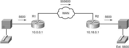
Tie-Line ConnectionIn traditional telephony networks, companies often had dedicated circuits called tie-lines connecting two PBXs. This, in effect, allowed callers at one site to reach callers at a remote site through that tie-line connection. Now that the IP network is replacing the traditional telephony connection, the two sites are logically tied together through the use of the connection tie-line command at both sites. Callers at one site can still reach callers at the remote site, but the call goes over the IP network. The connection tie-line command emulates tie-lines between PBXs. Although a tie-line connection is similar to a trunk connection, it is automatically set up for each call and torn down when the call ends. Another difference is that digits are added to the dial string before matching an outbound dial peer. For example, if a user were to dial extension 8000, which terminates at a remote office, the voice port is configured with an identifying number for that remote office. If that office ID is the number 7, then the digits that are sent to be matched against the outbound dial peer would be 78000. This new five-digit number would be carried across the network to the remote site. At the remote site, the number 7 can be stripped off or, if necessary, passed to the destination device. As demonstrated in Figure 4-16, with the syntax provided in Example 4-21 and Example 4-22, the following procedure is used to establish a tie-line connection:
Figure 4-16. Tie-Line Connection Example 4-21. Router R1's Configuration
Example 4-22. Router R2's Configuration
In Figure 4-16, the caller off of router R1 picks up the telephone and dials the four-digit extension, 5600. Because the voice port on router R2 is configured for connection tie-line, the router collects the four digits and prepends the tie-line digits 55 to make a six-digit number, 555600. That number is then matched to a VoIP dial peer and sent to the appropriate IP address. After the call reaches router R2, it is matched against a POTS dial peer with a destination pattern of 55.... Because POTS dial peers, by default, forward only wildcard digits, only the four-digit extension 5600 is passed to the PBX. |
EAN: 2147483647
Pages: 111