| Connecting voice devices to a network infrastructure requires an in-depth understanding of signaling and electrical characteristics that are specific to each type of interface. Improperly matched electrical components can cause echo and make a connection unusable. As another consideration, configuring devices for international implementation requires knowledge of country-specific settings. This section provides voice port configuration parameters for signaling and country-specific settings. Before delving into the specific syntax of configuring these voice ports, this section begins by considering several examples of voice applications. The applications discussed help illustrate the function of the voice ports, whose configuration is addressed at the end of this section. Voice Applications Different types of applications require specific types of ports. In many instances, the type of port is dependent on the voice device connected to the network. Different types of voice applications include the following: The following sections describe each type and provide an illustration of each. Local Calls Local calls, as illustrated in Figure 3-1, occur between two telephones connected to one Cisco voice-enabled router. This type of call is handled entirely by the router and does not travel over an external network. Both telephones are directly connected to Foreign Exchange Station (FXS) ports on the router. Figure 3-1. Local Calls 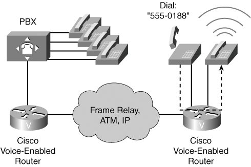
On-Net Calls On-net calls occur between two telephones on the same data network, as shown in Figure 3-2. The calls can be routed through one or more Cisco voice-enabled routers, but the calls remain on the same data network. The edge telephones attach to the network through direct connections and FXS ports, or through a PBX, which typically connects to the network via a T1 connection. IP phones that connect to the network via switches place on-net calls through Cisco Unified CallManager. The connection across the data network can be a LAN connection, as in a campus environment, or a WAN connection, as in an enterprise environment. Figure 3-2. On-Net Calls 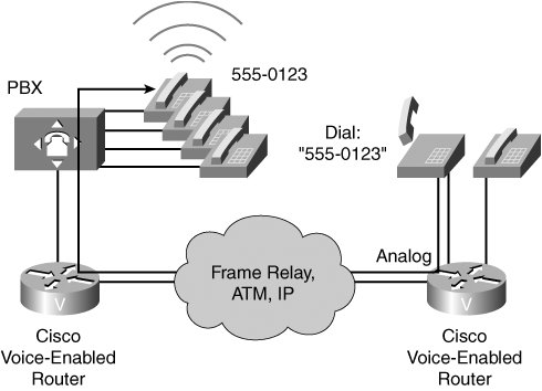
Off-Net Calls Figure 3-3 shows an example of an off-net call. To gain access to the public switched telephone network (PSTN), the user dials an access code, such as 9, from a telephone that is directly connected to a Cisco voice-enabled router or PBX. The connection to the PSTN is typically a single analog connection via a Foreign Exchange Office (FXO) port or a digital T1 or E1 connection. Figure 3-3. Off-Net Calls 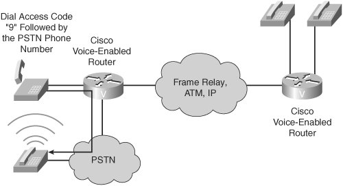
PLAR Calls PLAR calls automatically connect a telephone to a second telephone when the first telephone goes off hook, as depicted in Figure 3-4. When this connection occurs, the user does not get a dial tone because the voice-enabled port that the telephone is connected to is preconfigured with a specific number to dial. A PLAR connection can work between any types of signaling, including receive and transmit (ear and mouth [E&M]), FXO, FXS, or any combination of analog and digital interfaces. As an example, you might have encountered a PLAR connection at an airline ticket counter, where you pick up a handset and are immediately connected with an airline representative. Figure 3-4. PLAR Calls 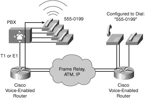
PBX-to-PBX Calls PBX-to-PBX calls, as shown in Figure 3-5, originate at a PBX at one site and terminate at a PBX at another site while using the network as the transport between the two locations. Many business environments connect sites with private tie trunks. When migrating to a converged voice and data network, this same tie-trunk connection can be emulated across the IP network. Modern PBX connections to the network are typically digital T1 or E1 with channel associated signaling (CAS) or PRI signaling, although PBX connections can also be analog. Figure 3-5. PBX-to-PBX Calls 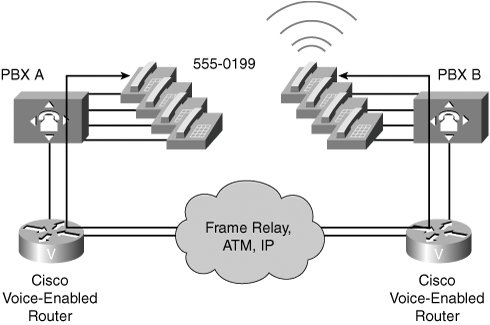
CallManager-to-CallManager Calls As part of an overall migration strategy, a business might replace PBXs with a Cisco Unified CallManager infrastructure. This infrastructure includes IP telephones that plug directly into the IP network. Cisco Unified CallManager performs the same call-routing functions formerly provided by the PBX. When an IP phone uses Cisco Unified CallManager to place a call, Cisco CallManager, based on its configuration, assesses whether the call is destined for another IP phone under its control or whether the call must be routed through a remote Cisco CallManager for call completion. Although the call stays on the IP network, it might be sent between zones. Every Cisco CallManager is part of a zone. A zone is a collection of devices that are under a common administration, usually a Cisco Unified CallManager or gatekeeper. Figure 3-6 provides an example of a CallManager-to-CallManager call. Figure 3-6. CallManager-to-CallManager Calls 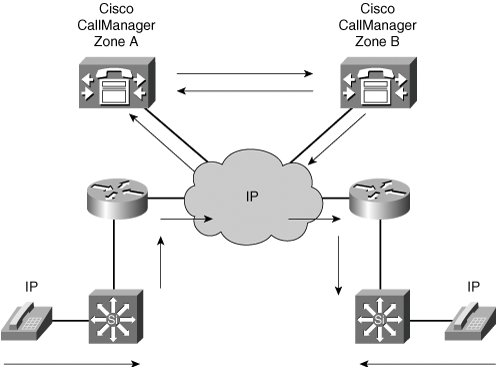
On-Net to Off-Net Calls When planning a resilient call-routing strategy, it might be necessary to reroute calls through a secondary path should the primary path fail. An on-net to off-net call, as illustrated in Figure 3-7, originates on an internal network and is routed to an external network, usually to the PSTN. On-net to off-net call-switching functionality might be necessary when a network link is down or if a network becomes overloaded and unable to handle all calls presented. Figure 3-7. On-Net to Off-Net Calls 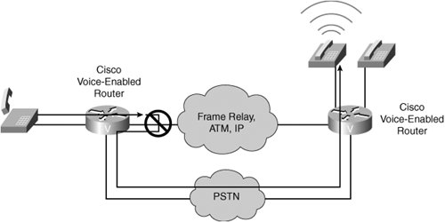
Summarizing Examples of Voice Port Applications Table 3-1 lists application examples for each type of call. Table 3-1. Voice Port Call TypesType of Call | Example |
|---|
Local call | One staff member calls another staff member at the same office. The call is switched between two ports on the same voice-enabled router. | On-net call | One staff member calls another staff member at a remote office. The call is sent from the local voice-enabled router, across the IP network, and terminated on the remote office voice-enabled router. | Off-net call | A staff member calls a client who is located in the same city. The call is sent from the local voice-enabled router, which acts as a gateway, to the PSTN. The call is then sent to the PSTN for call termination. | PLAR call | A client picks up a customer service telephone located in the lobby of an office and is automatically connected to a customer service representative without dialing any digits. The call is automatically dialed, based on the PLAR configuration of the voice port. In this case, as soon as the handset goes off hook, the voice-enabled router generates the prespecified digits to place the call. | PBX-to-PBX call | One staff member calls another staff member at a remote office. The call is sent from the local PBX, through a voice-enabled router, across the IP network, through the remote voice-enabled router, and terminated on the remote office PBX. | CallManager-to-CallManager call | One staff member calls another staff member at a remote office using IP phones. The call setup is handled by the Cisco Unified CallManagers at both locations. After the call is set up, the IP phones generate IP packets carrying voice between sites. | On-net to off-net call | One staff member calls another staff member at a remote office while the IP network is congested. When the originating voice-enabled router determines that it cannot terminate the call across the IP network, it sends the call to the PSTN with the appropriate dialed digits to terminate the call at the remote office via the PSTN network. |
FXS Ports FXS ports connect analog edge devices, such as analog phones, fax machines, and modems. In North America, the FXS port connection functions with default settings most of the time. The same cannot be said for other countries and continents. Remember, FXS ports look like switches to the edge devices that are connected to them. Therefore, the configuration of the FXS port should emulate the switch configuration of the local PSTN. For example, if the local PSTN uses loop-start signaling, the FXS port should use loop-start signaling. Consider the scenario of an international company with offices in the United States and England. The PSTN of each country provides signaling that is standard for that country. In the United States, the PSTN provides a dial tone that is different from the dial tone in England. Also, when the telephone rings to signal an incoming call, the ring is different in the United States. Another instance when the default configuration might be changed is when the connection is a trunk to a PBX or key system. In that case, the FXS port must be configured to match the settings of that device. FXS Configuration Parameters FXS port configuration allows you to set parameters based on the requirements of the connection. You can alter the default settings and fine-tune the parameters for specific needs. For example, you might need to connect an older phone with a mechanical ringer to a router, and the FXS port's default ringing frequency does not work for the older phone's ringer. You could adjust the ringing frequency parameter to fix that problem. You can set the following configuration parameters for an FXS port: signal Sets the signaling type for the FXS port. In most cases, the default signaling of loop-start works well. If the connected device is a PBX or a key system, the preferred signaling is ground start. Modern PBXs and key systems do not normally use FXS ports as connections to the network, but older systems might still have these interfaces. When connecting the FXS port to a PBX or key system, you must check the configuration of the voice system and set the FXS port to match the system setting. cptone Configures the appropriate call-progress tone for the local region. The call-progress tone setting determines the dial tone, busy tone, and ringback tone to the originating party. description Configures a description for the voice port. You can use the description setting to describe the voice port in show command output. It is almost always useful to provide some information about the usage of a port. The description could specify the type of equipment that is connected to the FXS port. ring frequency Configures a specific ring frequency (in Hz) for an FXS voice port. You must select the ring frequency that matches the connected equipment. If set incorrectly, the attached telephone might not ring or might buzz. In addition, the ring frequency is usually country dependent, and you should take into account the appropriate ring frequency for your area before you configure this command. Note Typically, the ring frequency parameter is an issue only for electromechanical bell ringers. Back in the days of party lines (that is, where multiple residences shared a local loop connection going back to the CO), these mechanical ringers were tuned to ring at different frequencies. However, most modern piezoelectric ringers are unaffected by the ring frequency setting.
ring cadence Configures the ring cadence for an FXS port. The ring cadence defines how ringing voltage is sent to signal a call. The normal ring cadence in North America is 2 seconds of ringing followed by 4 seconds of silence. The United Kingdom uses a double ring of 0.4 seconds separated by 0.2 seconds of silence, followed by 2 seconds of silence. When configured, the cptone setting automatically sets the ring cadence to match that country. You can manually set the ring cadence if you want to override the default country value. You might have to shut down and reactivate the voice port before the configured value takes effect. disconnect-ack Configures an FXS voice port to remove line power if the equipment on an FXS loop-start trunk disconnects first. This removal of line power is not something the user hears, but instead is a method for electrical devices to signal that one side has ended the call. busyout Configures the ability to busy out an analog port, perhaps for maintenance purposes. station id name Provides the station name associated with the voice port. This parameter is passed as a calling name to the remote end if the call is originated from this voice port. Maximum string length is limited to 15. station id number Provides the station number that is to be used as the calling number associated with the voice port. This parameter is optional and, if provided, will be used as the calling number if the call is originated from this voice port. If not specified, the calling number will be used from a reverse dial-peer search. Maximum string length is 15.
Configuring FXS Ports Figure 3-8 shows an FXS port of a router connecting into a PBX. Figure 3-8. FXS Voice Port Configuration 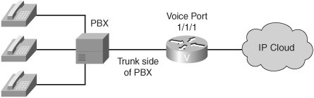
The syntax given in Example 3-1 shows how the British office, in Figure 3-8, is configured to enable ground-start signaling on a router on FXS voice port 1/1/1. Notice the call-progress tones are set for Great Britain, and the ring cadence is set for pattern 1. Example 3-1. FXS Voice Port Configuration on a Voice-Enabled Router Router#configure terminal Router(config)#voice-port 1/1/1 !Enters voice-port configuration mode Router(config-voiceport)#signal ground-start !Enables ground-start signaling Router(config-voiceport)#cptone GB !Sets call-progress tones for Great Britain Router(config-voiceport)#ring cadence pattern01 !Specifies ring cadence pattern 1
|
FXO Ports FXO ports act like telephones and connect to central office (CO) switches or to a station port on a PBX. This section describes FXO port configuration parameters and provides a sample FXO port configuration. FXO Configuration Parameters In most instances, the FXO port connection functions with default settings. FXO port configuration allows you to set parameters based on the requirements of the connection. As with FXS ports, you can alter default settings and fine-tune parameters. You can set the following configuration parameters for an FXO port: signal Sets the signaling type for the FXO port. If the FXO port is connected to the PSTN, the default setting of loop start is usually appropriate. If the FXO port is connected to a PBX, the signal setting must match the PBX. ring number Configures the number of rings before an FXO port answers a call. This is useful when you have other equipment available on the line to answer incoming calls. The FXO port answers if the equipment that is online does not answer the incoming call within the configured number of rings. dial-type Configures the appropriate dial type for outbound dialing. Older PBXs or key sets might not support dual-tone multifrequency (DTMF) dialing. If you are connecting an FXO port to this type of device, you might need to set the dial type for pulse dialing. description Configures a description for the voice port. Use the description setting to describe the voice port in show command output. supervisory disconnect Configures supervisory disconnect signaling on the FXO port. Supervisory disconnect signaling is a power denial from the switch that lasts at least 350 ms. When this condition is detected, the system interprets this as a disconnect indication from the switch and clears the call. You should disable supervisory disconnect on the voice port if there is no supervisory disconnect available from the switch. Typically, supervisory disconnect is available when connecting to the PSTN and is enabled by default. When the connection extends out to a PBX, you should verify the documentation to ensure that supervisory disconnect is supported.
Configuring FXO Ports Figure 3-9 shows a router's FXO port connecting into a PBX. Figure 3-9. FXO Voice Port Configuration 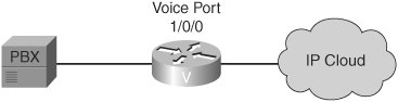
The configuration in Example 3-2 enables loop-start signaling on the router, on FXO voice port 1/0/0. The ring-number setting of 3 specifies that the FXO port does not answer the call until after the third ring, and the dial type is set to DTMF. Example 3-2. FXO Voice Port Configuration on a Voice-Enabled Router Router#configure terminal Router(config)#voice-port 1/0/0 !Enters voice-port configuration mode Router(config-voiceport)#signal loop-start !Enables loop-start signaling Router(config-voiceport)#ring number 3 !Sets FXO port to answer after three rings Router(config-voiceport)#dial-type dtmf !Specifies dial type of DTMF
|
E&M Ports E&M ports provide signaling that is used generally for switch-to-switch or switch-to-network trunk connections. This section describes E&M configuration parameters and provides an example of an E&M port configuration. E&M Configuration Parameters Although E&M ports have default parameters, you must usually configure these parameters to match the device that is connected to the E&M port. You can set the following configuration parameters: signal Configures the signal type for E&M ports which defines the signaling used when notifying a port to send dialed digits. This setting must match that of the PBX to which the port is connected. You must shut down and reactivate the voice port before the configured value takes effect. With wink-start signaling, the router listens on the M-lead to determine when the PBX wants to place a call. When the router detects current on the M-lead, it waits for availability of digit registers and then provides a short wink on the E-lead to signal the PBX to start sending digits. With delay-start, the router provides current on the E-lead immediately upon seeing current on the M-lead. When current is stopped for the digit-sending duration, the E-lead stays high until digit registers are available. With immediate-start, the PBX simply waits a short time after raising the M-lead and then sends the digits without a signal from the router. operation Configures the cabling scheme for E&M ports. The operation command affects the voice path only. The signaling path is independent of two-wire versus four-wire operation settings. If the wrong cable scheme is specified, the user might get voice traffic in one direction only. You must check with the PBX configuration to ensure that the settings match. You must then shut down and reactivate the voice port for the new value to take effect. type Configures the E&M interface type for a specific voice port. The type defines the electrical characteristics for the E- and M-leads. The E- and M-leads are monitored for on-hook and off-hook conditions. From a PBX perspective, when the PBX attempts to place a call, it goes high (off hook) on the M-lead. The switch monitors the M-lead and recognizes the request for service. If the switch attempts to pass a call to the PBX, the switch goes high on the E-lead. The PBX monitors the E-lead and recognizes the request for service by the switch. To ensure that the settings match, you must check them against the PBX configuration. auto-cut-through Configures the ability to enable call completion when a PBX does not provide an M-lead response. For example, when the router is placing a call to the PBX, even though they might have the same correct signaling configured, not all PBXs provide the wink with the same duration or voltage. Therefore, the router might not understand the PBX wink. The auto-cut-through command allows the router to send digits to the PBX, even when the expected wink is not detected. description Configures a description for the voice port. Use the description setting to describe the voice port in show command output.
Configuring E&M Ports Figure 3-10 shows a router's E&M port connecting to a PBX's E&M interface. Figure 3-10. E&M Voice Port Configuration 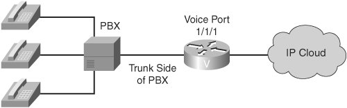
The configuration in Example 3-3 enables wink-start signaling on the router, on E&M voice port 1/1/1. The operation is set for the two-wire voice-cabling scheme, meaning the voice path consists of two wires, and the type is set to 1. Example 3-3. E&M Voice Port Configuration on a Voice-Enabled Router Router#configure terminal Router(config)#voice port 1/1/1 !Enters voice port configuration mode Router(config-voiceport)#signal wink-start !Enables Wink-Start signaling Router(config-voiceport)#operation 2-wire !Sets operation for two-wire cabling scheme Router(config-voiceport)#type 1 !Configures type 1 E&M port
|
Timers and Timing A variety of default timer settings are configured for various voice ports. Under normal use, these timers do not need adjusting. In instances where ports are connected to a device that does not properly respond to dialed digits or hookflash (that is, quickly transitioning from the off-hook state to the on-hook state and back to the off-hook state) or where the connected device provides automated dialing, these timers can be configured to allow more or less time for a specific function. Timers and Timing Configuration Parameters You can set a number of timers and timing parameters for fine-tuning the voice port. Following are voice port configuration parameters that you can set: timeouts initial Configures the initial digit timeout value in seconds. This value controls how long the dial tone is presented before the first digit is expected. This timer typically does not need to be changed from its default of 10 seconds. timeouts interdigit Configures the number of seconds for which the system will wait for the caller to input a subsequent digit of the dialed digits after the caller has input the initial digit. If the digits are coming from an automated device and the dial plan is a variable-length dial plan, you can shorten this timer so that the call proceeds without having to wait the full default of 10 seconds for the interdigit timer to expire. timeouts ringing Configures the length of time that a caller can continue ringing a telephone when there is no answer. You can configure this setting to be less than the default of 180 seconds so that you do not tie up the voice port when it is evident that the call is not going to be answered. timing digit Configures the DTMF digit-signal duration for a specified voice port. You can use this setting to fine-tune a connection to a device that might have trouble recognizing dialed digits. If a user or device dials too quickly, the digit might not be recognized. By changing the timing on the digit timer, you can provide for a shorter or longer DTMF duration. timing interdigit Configures the DTMF interdigit duration for a specified voice port. You can change this setting to accommodate faster or slower dialing characteristics. timing hookflash-in and hookflash-out Configures the maximum duration (in milliseconds) of a hookflash indication. Hookflash is an indication by a caller that the caller wishes to do something specific with the call, such as transfer the call or place the call on hold. For hookflash-in, if the hookflash lasts longer than the specified limit, the FXS interface processes the indication as on hook. If you set the value too low, the hookflash might be interpreted as a hang up; if you set the value too high, the handset has to be left hung up for a longer period to clear the call. For hookflash-out, the setting specifies the duration (in milliseconds) of the hookflash indication that the gateway generates outbound. You can configure this to match the requirements of the connected device.
Configuring Timers The installation in Figure 3-11 serves as a solution in a home for the elderly, where users might need more time to dial digits than in other residences. Also, there is a requirement to allow the telephone to ring, unanswered, for only one minute. Figure 3-11 shows an analog phone connecting into FXS port 1/0/0 on a voice-enabled router. Figure 3-11. Timers and Timing Configuration 
The FXS port's configuration, as shown in Example 3-4, enables several timing parameters for this voice port. The initial timeout is lengthened to 15 seconds, the interdigit timeout is lengthened to 15 seconds, the ringing timeout is set to 60 seconds, and the hookflash-in timer is set to 500 ms. Example 3-4. Timer Voice Port Configuration on a Voice-Enabled Router Router#configure terminal Router(config)#voice-port 1/0/0 !Enters voice-port configuration mode Router(config-voiceport)#timeouts initial 15 !Sets initial timeout to 15 seconds Router(config-voiceport)#timeouts interdigit 15 !Sets interdigit timeouts to 15 seconds Router(config-voiceport)#timeouts ringing 60 !Sets ringing timeout to 60 seconds Router(config-voiceport)#timing hookflash-in 500 !Sets hookflash-in to 500 ms duration
|
Digital Voice Ports While analog voice ports typically carry a single voice call on a single port, digital voice ports often carry multiple voice conversations over a single voice port. Therefore, digital voice ports might be more appropriate for environments with a high call volume. As a rule of thumb, if a design requires more than seven voice connections, the designer should consider a digital voice port, as opposed to multiple analog voice ports, due to the economies of scale offered by the higher-density digital voice ports. Digital Voice Configuration Parameters When you purchase a T1 or E1 connection, make sure that your service provider gives you the appropriate settings. Before you configure a T1 or E1 controller to support digital voice ports, you must enter the following basic configuration parameters to bring up the interface: framing Selects the frame type for a T1 or E1 data line. The framing configuration differs between T1 and E1, as follows: - - Options for T1 Super Frame (SF) or Extended Superframe (ESF). SF is the default.
- - Options for E1 4-bit cyclic redundancy check (CRC4), no-CRC4, or Australia. CRC4 is the default.
linecode Configures the line-encoding format for the DS1 link. The linecode configuration differs for T1 and E1, as follows: - - Options for T1 Alternate mark inversion (AMI) or binary 8-zero substitution (B8ZS). AMI is the default.
- - Options for E1 AMI or high-density binary 3 (HDB3). HDB3 is the default.
clock source Configures clocking for individual T1 or E1 links. Line and internal are the options for both T1 and E1. Line is the default.
You must create a digital voice port in the T1 or E1 controller to make the digital voice port available for specific voice port configuration parameters. You must also assign timeslots and signaling to the logical voice port. The first step is to create the T1 or E1 digital voice port with the ds0-group ds0-group-no timeslots timeslot-list type signal-type command. The following list describes the command syntax: The ds0-group command automatically creates a logical voice port that is numbered as slot/port:ds0-group-no. The ds0-group-no parameter identifies the DS0 group (number from 0 to 23 for T1 and from 0 to 30 for E1). This group number is used as part of the logical voice port numbering scheme. The timeslots command allows the user to specify which timeslots are part of the DS0 group. The timeslot-list parameter is a single timeslot number, a single range of numbers, or multiple ranges of numbers separated by commas. The type command defines the emulated analog signaling method that the router uses to connect to the PBX or PSTN. The type depends on whether the interface is T1 or E1. The signal-type parameter is the signaling type being used by all channels in the DS0 group. For example, the signaling type could be configured as e&m-wink-start, which would cause each channel in the DS0 group to use E&M wink-start signaling.
After you specify a ds0-group command, the system creates a logical voice port. You must then enter the voice-port configuration mode to configure port-specific parameters. To enter voice port configuration mode, use the voice-port slot/port:ds0-group-no command. To delete a DS0 group, you must first shut down the logical voice port. When the port is in shutdown state, you can remove the DS0 group from the T1 or E1 controller with the no ds0-group ds0-group-no command. Configuring a T1 Controller Figure 3-12 illustrates how specific channels within a T1 can be defined as a DS0 group. Figure 3-12. Digital Voice Configuration 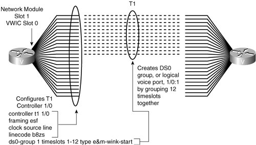
The syntax for the topology shown is presented in Example 3-5. The example configures the T1 controller for ESF framing, B8ZS line coding, and timeslots 1 through 12 with E&M wink-start signaling. The resulting logical voice port is 1/0:1, where 1/0 is the module and slot number and :1 is the ds0-group-no value that was assigned during configuration. You can configure the remaining timeslots for other signaling types or leave them unused. Example 3-5. DS0 Group Configuration on a Voice-Enabled Router| [View full width] Router#configure terminal Router(config)#controller t1 1/0 !Enters controller configuration mode Router(config-controller)#framing esf !Sets the framing to Extended Superframe Router(config-controller)#clock source line !Specifies that the controller receives clocking from the network Router(config-controller)#linecode b8zs !Sets the linecoding to Bipolar 8 Zero Substitution Router(config-controller)#ds0-group 1 timeslots 1-12 type e&m-wink-start !Defines a DS0 group, which contains the first 12 channels of the T1, and configures the  signaling for those channels as E&M Wink Start signaling signaling for those channels as E&M Wink Start signaling
|
ISDN Cisco voice-capable devices provide support for both PRI and BRI voice connections. Many PBX vendors support either T1/E1 PRI or BRI connections. In Europe, where ISDN is more popular, many PBX vendors support BRI connections. When designing how the PBX passes voice to the network, you must ensure that the router supports the correct connection. ISDN Configuration Parameters The first step in configuring ISDN capabilities for T1 or E1 PRI is to configure the T1 or E1 controller basics. After the clock source, framing, and line code are configured, ISDN voice functionality requires the following configuration commands: isdn switch-type Configures the ISDN switch type. You can enter this parameter in global configuration mode or in interface configuration mode. If you configure both, the interface switch type takes precedence over the global switch type. This parameter must match the provider ISDN switch. This setting is required for both BRI and PRI connections. pri-group Configures timeslots for the ISDN PRI group. T1 allows for timeslots 1 to 23, with timeslot 24 allocated to the D channel. E1 allows for timeslots 1 to 31, with timeslot 16 allocated to the D channel. You can configure the PRI group to include all available timeslots, or you can configure a select group of timeslots for the PRI group. isdn incoming-voice voice Configures the interface to send all incoming calls to the digital signal processor (DSP) card for processing. QSIG signaling Configures the use of Q Signaling (QSIG) signaling on the D channel. You typically use this setting when connecting via ISDN to a PBX. The command to enable QSIG signaling is isdn switch-type primary-qsig for PRI and isdn switch-type basic-qsig for BRI connections.
Configuring ISDN Figure 3-13 shows an ISDN port on a voice-enabled router connecting into an ISDN port on a PBX. Figure 3-13. ISDN Configuration 
Example 3-6 shows the configuration for this connection. The connection is configured for QSIG signaling across all 23 timeslots. Example 3-6. ISDN Voice Port Configuration on a Voice-Enabled Router Router (config)#isdn switch-type primary-qsig !QSIG signaling support Router (config)#controller T1 0/0 Router (config-controller)#pri-group timeslots 1-23 !PRI timeslot allocation Router (config)#interface serial 0/0:23 Router (config-if)#isdn incoming-voice voice !Sends incoming calls to DSPs
|
Common Channel Signaling Options Proprietary signaling can be passed between two PBXs through the use of Transparent Common Channel Signaling (T-CCS), an example of which is provided in Figure 3-14. Figure 3-14. CCS Options 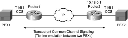
The syntax for the configuration shown is provided in Example 3-7. The dial-peer and voice-port commands are covered in Chapter 4, "Voice Dial Peer Configuration." For now, consider the ds0-group 1 timeslots 24 type ext-sig command, entered in controller configuration mode. This command specifies that the 24th channel of the T1 is going to be carrying external signaling, which the router should not attempt to interpret. Also, notice the codec clear-channel command. This command tells the router to pass the signaling information through the DSP transparently, without any compression or processing. Example 3-7. Transparent Common Channel Signaling Configuration Router(config)#controller T1 1/0 Router(config-controller)#ds0-group 1 timeslots 24 type ext-sig !Configures the signaling channel for external signaling Router(config-controller)#exit Router config)#dial-peer voice 1 voip !Creates a VoIP dial peer Router(config-dialpeer)#codec clear-channel !Specifies clear-channel CODEC to pass signaling through the DSP without !compression or processing Router(config-dialpeer)#destination-pattern 1000 !Specifies a destination pattern Router(config-dialpeer)#session target ipv4:10.18.0.1 !Specifies IP address of remote site router Router(config-dialpeer)#exit Router(config)#voice-port 1/0:1 Router(config-voiceport)#connection trunk 1000 answer-mode !Creates a trunk on voice-port 1/0:1 and ties it to the VoIP dial peer with !a destination pattern of 1000
|
In many cases, PBXs support proprietary signaling that is used to signal supplementary services only, such as making a light on the telephone blink when voice mail is waiting. Because the router does not understand this proprietary signaling, the signaling must be carried transparently across the network without interpretation. T-CCS allows the connection of two PBXs with digital interfaces that use a proprietary or unsupported common channel signaling (CCS) protocol. T1 and E1 traffic is transported transparently through the data network, and the T-CCS feature preserves proprietary signaling. From the PBX stand-point, this type of communication is accomplished through a point-to-point connection. The configuration for T-CCS in a Voice over IP (VoIP) environment calls for the following three-step process: 1. | To define the DS0 group, configure the command ds0-group ds0-group-no timeslots timeslot-list type ext-sig in the T1 or E1 controller configuration mode. The timeslots command specifies the D channel that carries call signaling. The type ext-sig command specifies that the signaling is coming from an external source.
| 2. | Create the dial peer, as follows:
Configure a VoIP dial peer that points to the IP address of the remote voice-enabled router that connects to the remote PBX. Configure the dial peer for clear-channel codec that signals the DSP to pass the signaling without interpretation. Specify the destination pattern for the dial peer, which is used to create the trunk in Step 3. The number entered here must match the number entered in the trunk command. Configure the session target to point to the IP address of the remote voice-enabled router. Configure the dial peer to point to the IP address of the remote site voice-enabled router using the session target command.
| 3. | Create the voice port trunk.
|
Note Chapter 4 covers dial peers in depth.
Configure the connection trunk digits answer-mode command at the logical voice port to create a trunk from that port through the VoIP dial peer and across the IP network to the remote router. The digits parameter must match the destination pattern in the VoIP dial peer created in Step 2. The answer-mode parameter specifies that the router should not attempt to initiate a trunk connection but should wait for an incoming call before establishing the trunk. The process for passing the signal transparently through the IP network is as follows: 1. | PBX1 sends proprietary signaling across the signaling channel to router 1.
| 2. | The logical voice port that corresponds to the signaling channel is configured for trunking, so the router looks for the dial peer that matches the trunk digits parameter.
| 3. | The VoIP dial peer is configured for clear-channel codec and points to the IP address of the remote router (router 2) connecting the remote PBX (PBX2).
| 4. | The remote router has a plain old telephone service (POTS) dial peer configured that points to the logical voice port associated with the signaling channel of PBX2. The signal arrives at PBX2 in its native form.
|
This process shows the T-CCS signaling part of the configuration only. Additional DS0 group and dial-peer configuration is necessary for transport of the voice channels. Monitoring and Troubleshooting After physically connecting analog or digital devices to a Cisco voice-enabled router, you might need to issue show, test, or debug commands to verify or troubleshoot your configuration. For example, the following list enumerates six steps to monitor and troubleshoot voice ports: 1. | Pick up the handset of an attached telephony device and check for a dial tone. If there is no dial tone, check the following:
Is the plug firmly seated? Is the voice port enabled? Is the voice port recognized by the Cisco IOS? Is the router running the correct version of Cisco IOS in order to recognize the module?
| | | 2. | If you have a dial tone, check for DTMF voice band tones, such as touch-tone detection. If the dial tone stops when you dial a digit, the voice port is probably configured properly.
| 3. | Use the show voice port command to verify that the data configured is correct. If you have trouble connecting a call and you suspect that the problem is associated with voice port configuration, you can try to resolve the problem by performing Steps 4 through 6
| 4. | Use the show voice port command to make sure that the port is enabled. If the port is administratively down, use the no shutdown command. If the port was working previously and is not working now, it is possible that the port is in a hung state. Use the shutdown/no shutdown command sequence to reinitialize the port.
| 5. | If you have configured E&M interfaces, make sure that the values associated with your specific PBX setup are correct. Specifically, check for two-wire or four-wire wink-start, immediate-start, or delay-start signaling types, and the E&M interface type. These parameters need to match those set on the PBX for the interface to communicate properly.
| 6. | You must confirm that the voice network module (VNM) (that is, the module in the router that contains the voice ports) is correctly installed. With the device powered down, remove the VNM and reinsert it to verify the installation. If the device has other slots available, try inserting the VNM into another slot to isolate the problem. Similarly, you must move the voice interface card (VIC) to another VIC slot to determine if the problem is with the VIC card or with the module slot.
|
For your reference, Table 3-2 lists six show commands for verifying the voice port configuration. Table 3-2. Commands to Verify Voice PortsCommand | Description |
|---|
show voice port | Shows all voice port configurations in detail | show voice port slot/subunit/port | Shows one voice port configuration in detail | show voice port summary | Shows all voice port configurations in brief | show voice busyout | Shows all ports configured as busyout | show voice dsp | Shows status of all DSPs | show controller T1 | E1 | Shows the operational status of a controller |
For your further reference, Table 3-3 provides a series of commands used to test Cisco voice ports. The test commands provide the ability to analyze and troubleshoot voice ports on voice-enabled routers. As Table 3-3 shows, there are five test commands to force voice ports into specific states to test the voice port configuration. The csim start dial-string command simulates a call to any end station for testing purposes. Table 3-3. test CommandsCommand | Description |
|---|
test voice port port_or_DS0-group_identifier detector {m-lead | battery-reversal | ring | tip-ground | ring-ground | ring-trip} {on | off | disable} | Forces a detector into specific states for testing. | test voice port port_or_DS0-group_identifier inject-tone {local | network} {1000hz | 2000hz | 200hz | 3000hz | 300hz | 3200hz | 3400hz | 500hz | quiet | disable} | Injects a test tone into a voice port. A call must be established on the voice port under test. When you are finished testing, be sure to enter the disable command to end the test tone. | test voice port port_or_DS0-group_identifier loopback {local | network | disable} | Performs loopback testing on a voice port. A call must be established on the voice port under test. When you finish the loopback testing, be sure to enter the disable command to end the forced loopback. | test voice port port_or_DS0-group_identifier relay {e-lead | loop | ring-ground | battery-reversal | power-denial | ring | tip-ground} {on | off | disable} | Tests relay-related functions on a voice port. | test voice port port_or_DS0-group_identifier switch {fax | disable} | Forces a voice port into fax or voice mode for testing. If the voice port does not detect fax data, the voice port remains in fax mode for 30 seconds and then reverts automatically to voice mode. After you enter the test voice port switch fax command, you can use the show voice call command to check whether the voice port is able to operate in fax mode. | csim start dial-string | Simulates a call to the specified dial string. It is most useful when testing dial plans. |
Table 3-4 lists ISDN show and debug commands specific to the monitoring and troubleshooting of ISDN connections. Table 3-4. ISDN CommandsCommand | Description |
|---|
show isdn active | Shows ISDN calls in progress | show isdn history | Shows ISDN call history | show isdn status | Shows ISDN line status | show isdn timers | Shows ISDN timer values | debug isdn events | Displays ISDN events in real time | debug isdn q921 | Displays ISDN Q.921 packets in real time | debug isdn q931 | Displays ISDN Q.931 packets in real time |
Tuning Voice Quality User acceptance of the converged voice and data network depends on the quality of current calls compared to the quality through their original providers. As new devices are introduced in the voice path, it is important to understand how the electrical characteristics of interfaces impact voice quality. This section discusses these electrical characteristics and how to fine-tune them for improved voice quality. Electrical Characteristics Voice signal power in a long-distance connection must be tightly controlled. The delivered signal power must be high enough to be clearly understood, but not so strong that it leads to instabilities such as echo. In the traditional telephony network, telephone companies control the signal power levels at each analog device. Now that the IP network is carrying voice, it might be necessary to adjust signal power on a voice interface to fine-tune the voice quality. Echo Most initial voice signals enter the network through a two-wire local loop. Most switches connect to other switches through a four-wire connection. As voice travels through the network for delivery to the remote telephone, the voice signal must be passed from the two-wire local loop to the four-wire connection at the first switch, and from the four-wire connection at the switch to a two-wire local loop at the remote end. If the impedance at these two-wire to four-wire connections is not matched exactly, some of the voice signal reflects back in the direction of the source. As a result, originating callers hear their own voice reflected back. Sometimes, the reflected signal is reflected again, causing the destination to hear the same conversation twice. In a traditional voice network, voice can reflect back. It usually goes unnoticed, however, because the delay is so low. In a VoIP network, echo is more noticeable because both packetization and compression contribute to delay. Specifically, for echo to be a problem, all of the following conditions must exist: An analog leakage path between analog Tx and Rx paths Sufficient delay in echo return for echo to be perceived as annoying Sufficient echo amplitude to be perceived as annoying
Two types of echo might exist in a telephony network: talker echo and listener echo. Talker echo, which is the most common type of echo, occurs when the speech energy of a talker, transmitted down the primary signal path, is coupled into the receiving path from the far end (or tail circuit), as illustrated in Figure 3-15. Talkers then hear their own voice, delayed by the total echo path delay time. If the "echoed""signal has sufficient amplitude and delay, the result can be annoying to the user and can interfere with the normal speech process. Talker echo is usually a direct result of the two-wire to four-wire conversion that takes place through "hybrid" transformers. Figure 3-15. Talker Echo 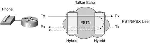
Listener echo is less common than talker echo. As shown in Figure 3-16, listener echo occurs at the far end by circulating voice energy and is generally caused by the two-wire and four-wire hybrid transformers (caused by the "echo being echoed"). The voice of the talker is echoed by the far-end hybrid, and when the echo comes back to the listener, the hybrid on the side of the listener echoes the echo back toward the listener. The effect is that the person listening hears both the talker and an echo of the talker. Figure 3-16. Listener Echo 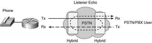
Signal Strength Another problem is inconsistent volume at different points in the network. Both echo and volume inconsistency might be caused by a voice port generating a signal level that is too high or too low. You can adjust signal strength, either in the inbound direction from an edge telephone or switch into the voice port, or in the outbound direction from the voice port to the edge telephone or switch. Echo results from incorrect input or output levels, or from an impedance mismatch. Although these adjustments are available on the Cisco voice equipment, they are also adjustable on PBX equipment. Too much input gain can cause clipped or fuzzy voice quality. If the output level is too high at the remote router voice port, the local caller hears echo. If the local router voice port input decibel level is too high, the remote side hears clipping. If the local router voice port input decibel level is too low, or the remote router output level is too low, the remote-side voice can become distorted at a very low volume and DTMF tones might be missed. Calculating Decibel Levels Change in signal strength is measured in decibels (dBs). You can either boost the signal or attenuate it by configuring the voice port for input gain or output attenuation. You must be aware of what a voice port connects to and know at what dB level that device works best. Calculating network dB levels is often an exercise in simple number line arithmetic. Table 3-5 provides common dB levels. Table 3-5. Calculating Decibel LevelsSource 1 Out/In | Router 1 Adjustment | Net at Router 1 | WAN | Net at Router 2 | Router 2 Adjustment | Destination 1 In/Out |
|---|
0 dB  | -3 dB | -3 dB | -- | -3 dB | +/-6 dB | -9 dB | -9 dB  | +/- 6 dB | -3 dB | -- | -3 dB | -3 dB |  0 dB 0 dB
|
Baselining Input and Output Power Levels Considerations for baselining input and output power levels are as follows: Analog voice routers operate best when the receive level from an analog source is set at approximately 3 dB. In the United States and most of Europe, the receive level normally expected for an analog telephone is approximately 9 dB. In Asian and South American countries, receive levels are closer to 14 dB. To accommodate these differences, the output levels to the router are set over a wide range. Overdriving the circuit can cause analog clipping. Clipping occurs when the power level is above available pulse code modulation (PCM) codes, and a continuous repetition of the last PCM value is passed to the DSP. Echo occurs when impedance mismatches reflect power back to the source.
Adjustment of decibel levels might be necessary throughout a voice network. A station connected to a PBX might experience one level of loudness when calling a local extension, a different level when dialing an outside line, and different levels when calling remote sites via VoIP. Adjustments might be necessary in this case. Voice Port Tuning In an untuned network, a port configuration that delivers perceived good quality for a call between two dial peers might deliver perceived poor quality for a call between two other dial peers. Voice quality adjustment is a defined, step-by-step procedure that is implemented after the network is up and running. It is ineffective for you to begin changing the default voice port configurations until full cross-network calls are established; a correctly implemented procedure results in a quality compromise between various sources that the customer accepts as good overall quality. A variety of different factors, including input gain and output attenuation, can affect voice quality, as illustrated in Figure 3-17. Notice that input gain occurs as the signal goes into the echo canceller, and output attenuation occurs as the signal comes out of the echo canceller. Figure 3-17. Configuring Voice Port Voice-Quality Tuning 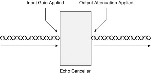
A loss plan looks at the required dB levels at specific interfaces, such as an analog FXS port connecting to a telephone or an FXO port connecting to the PSTN. An analog voice router works best with a receive level of 3 dB. An analog telephone in North America and Europe works best with a receive level of 9 dB. Therefore, if the device connecting to that router provides a different level than the expected 3 dB, then input gain can be set to equalize it to 3 dB. If the output at the other end is a telephone that expects 9 dB, then the output voice port has to provide 6 dB output attenuation in addition to the 3 dB to send signaling to the telephone at the expected 9 dB levels. A system-wide loss plan looks at the dB levels of the initial input and the remote output ports and plans for the appropriate adjustments for end-to-end signal levels. You must consider other equipment (including PBXs) in the system when creating a loss plan. Voice Port Tuning Configuring Parameters Parameters for configuring voice port voice quality tuning are as follows: input-gain Configures a specific input gain, in decibels, to insert into the receiver side of the interface. The default value for this command assumes that a standard transmission loss plan is in effect, meaning that there must be an attenuation of 6 dB between telephones. The standard transmission plan defines country-specific dB levels and assumes that interfaces already provide the expected dB levels. For example, there must be attenuation of 6 dB between two telephones so that the input gain and output attenuation is 0, if the interfaces provide the required 6 dB attenuation. output-attenuation Configures the output attenuation value in decibels for the transmit side. The value represents the amount of loss to be inserted at the transmit side of the interface. impedance Configures the terminating impedance of a voice port interface. The impedance value selected must match the setting from the specific telephony system or device to which it is connected. Impedance standards vary between countries. CO switches in the United States are predominantly 600 ohms real (600r). PBXs in the United States are normally 600r or 900 ohms complex (900c). Incorrect impedance settings or an impedance mismatch generates a significant amount of echo. You can mask the echo by entering the echo-cancel command. In addition, gains often do not work correctly if there is an impedance mismatch.
Note The input-gain and output-attenuation commands accommodate network equipment and are not end-user volume controls for user comfort.
Configuring Voice Port Tuning Figure 3-18 shows a voice-enabled router connecting to a PBX via an E&M port, specifically, port 1/0/0. Additionally, the router connects into the PSTN via FXO port 1/1/0. Figure 3-18. Voice Port Tuning Example 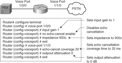
Example 3-8 illustrates voice port tuning parameters on the E&M and FXO ports in the router shown in Figure 3-18. In the example, the PBX output is 4 dB, whereas the voice router functions best at 3 dB. Therefore, the adjustment is made in the inbound path to the router using the input-gain command. The impedance setting on the router needs to be changed from the default of 600r to match the 900c impedance setting of the PBX. Because this is an E&M port, echo cancellation is disabled. The FXO port connecting to the PSTN has an adjustment for echo coverage that allows for longer-distance echo cancellation. Example 3-8. Configuring Voice Port Tuning Router#configure terminal Router(config)#voice-port 1/0/0 Router (config-voiceport)#input gain 1 !Sets input gain to 1 Router (config-voiceport)#no echo-cancel enable !Disables echo cancellation Router (config-voiceport)#impedance 900c !Sets impedance to 900c Router (config-voiceport)#exit Router(config)#voice-port 1/1/0 Router (config-voiceport)#output attenuation 0 !Sets output attenuation to 0 decibels Router (config-voiceport)#exit
|
E&M voice port parameters used in Example 3-8 include: input-gain Increases the inbound voice level by 1 dB before the voice is transmitted across the network no echo-cancel enable Disables echo cancellation impedance Sets the impedance to match the connecting hardware
FXO voice port parameters used in Example 3-8 include: echo-cancel coverage Adjusts the cancellation coverage time to 32 ms. This allows for cancellation of echo that has greater delay. output-attenuation Specifies that there is no attenuation as the signal is passed out of the interface to the PSTN.
|