IP Telephony Applications
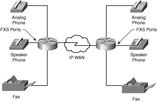
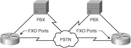
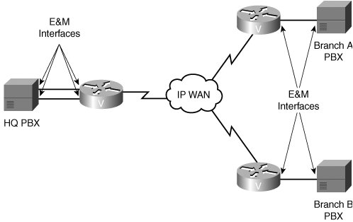
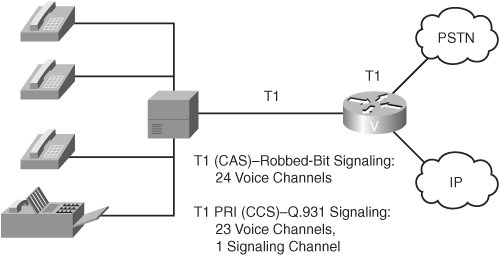
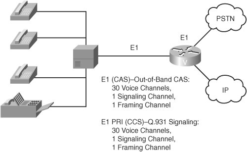
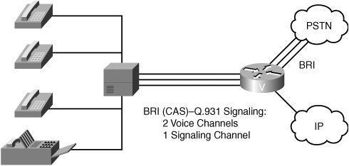
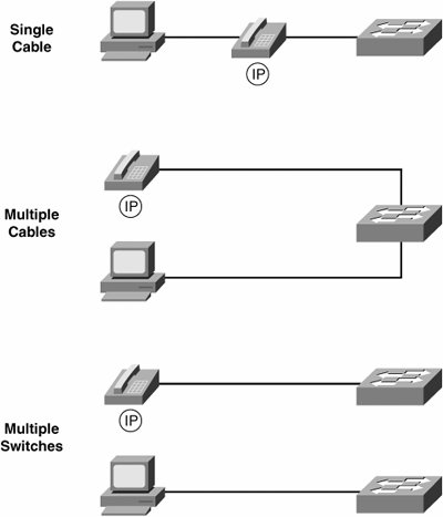
| As customers migrate their voice networks, they face a myriad of choices regarding interface types, components, and topologies. A good network design incorporates solutions for current requirements and allows room for future growth. It is important to understand how voice interfaces with a network and how the components fit together to provide service in any environment. Analog InterfacesA Foreign Exchange Station (FXS) interface, as depicted in Figure 1-16, provides a direct connection to an analog telephone, a fax machine, or a similar device. From a telephone perspective, the FXS interface functions like a telephone switch (for example, a PBX); therefore, it must supply line power, ring voltage, and dial tone. Figure 1-16. Foreign Exchange Station (FXS) Interface The FXS interface contains the coder-decoder (CODEC), which converts the spoken analog voice wave into a digital format for processing by the voice-enabled device. The Foreign Exchange Office (FXO) interface, shown in Figure 1-17, allows an analog connection to be directed at the CO of a PSTN or to a station interface on a PBX. The switch recognizes the FXO interface as a telephone because the interface plugs directly into the line side of the switch. The FXO interface provides either pulse or DTMF digits for outbound dialing. Figure 1-17. Foreign Exchange Office (FXO) Interface In PSTN terminology, an FXO-to-FXS connection is also referred to as a foreign exchange (FX) trunk. An FX trunk is a CO trunk that has access to a distant CO. Because this connection is FXS at one end and FXO at the other end, it acts as a long-distance extension of a local telephone line. In this instance, a local user can pick up the telephone and get a dial tone from a foreign city. Users in the foreign city can dial a local number and have the call connect to the user in the local city. The E&M interface, shown in Figure 1-18, provides signaling for analog trunking. Analog trunk circuits connect automated systems (PBXs) and networks (COs). E&M signaling is also referred to as "ear and mouth," but its origin comes from the term "Earth and Magneto." Earth represents the electrical ground, and magneto represents the electromagnet used to generate tone. Figure 1-18. Earth and Magneto (E&M) Interface E&M signaling defines a trunk-circuit side and a signaling-unit side for each connection, similar to the DCE and DTE reference types. The PBX is usually the trunk-circuit side, and the telco, CO, channel bank, or Cisco voice-enabled platform is the signaling-unit side. Digital InterfacesIn a corporate environment with a large volume of voice traffic, connections to the PSTN and to PBXs are primarily digital. Examples of digital interfaces include T1, E1, and BRI interfaces. T1 InterfaceA T1 interface, as illustrated in Figure 1-19, is a form of digital connection that can simultaneously carry up to 24 conversations using two-wire pairs. When a T1 link operates in full-duplex mode, one wire pair sends and the other wire pair receives. The 24 channels are grouped together to form a frame. The frames are then grouped together into Super Frames (groups of 12 frames) or into Extended Superframes (groups of 24 frames). Figure 1-19. T1 Interface The T1 interface carries either CAS or CCS. When a T1 interface uses CAS, the signaling robs a sampling bit for each channel to convey in band. When a T1 interface uses CCS, Q.931 signaling is used on a single channel, typically the last channel. To configure CAS, you must specify the type of signaling that the robbed bits carry (for example, E&M Wink Start). This signaling must match the PSTN requirements or the PBX configuration. This is considered in-band signaling because the signal shares the same channel as the voice. To configure CCS, you must configure the interface for PRI signaling. This level of configuration makes it possible to use channels 1 to 23 (called B channels) for voice traffic. Channel 24 (called the D channel) carries the Q.931 call control signaling for call setup, maintenance, and teardown. This type of signaling is considered out-of-band signaling because the Q.931 messages are sent in the D channel only. E1 InterfaceAn E1 interface, shown in Figure 1-20, has 32 channels and simultaneously carries up to 30 conversations. The other two channels are used for framing and signaling. The 32 channels are grouped to form a frame. The frames are then grouped together into multiframes (groups of 16 frames). In Europe and Mexico, the E1 interface is most often used, while in the United States the T1 interface is most commonly used. Figure 1-20. E1 Interface Although you can configure the E1 interface for either CAS or CCS, the most common usage is CCS. When an E1 interface uses CAS, signaling travels out of band in the signaling channel but follows a strict association between the signal carried in the signaling channel and the channel to which the signaling is being applied. The signaling channel is channel 16. In the first frame, channel 16 carries 4 bits of signaling for channel 1 and 4 bits of signaling for channel 17. In the second frame, channel 16 carries 4 bits of signaling for channel 2 and 4 bits for channel 18, and so on. This process makes it out-of-band CAS. When an E1 interface uses CCS, Q.931 signaling is used on a single channel, typically channel 17. When configuring for CCS, configure the interface for PRI signaling. When E1 is configured for CCS, channel 16 carries Q.931 signaling messages only. BRI InterfaceFigure 1-21 depicts an Integrated Services Digital Network (ISDN) Basic Rate Interface (BRI). You can use a BRI to connect the PBX voice into the network. Used primarily in Europe for PBX connectivity, BRI provides a 16-kbps D channel for signaling and two 64-kbps B channels for voice. BRI uses Q.931 signaling in the D channel for call signaling. Figure 1-21. Basic Rate Interface (BRI) IP PhonesFigure 1-22 depicts physical connection options for IP phones. The IP phone connects to the network through a Category 5 or better cable that has RJ-45 connectors. The power-enabled switch port or an external power supply provides power to an IP phone. The IP phone functions like other IP-capable devices sending IP packets to the IP network. Because these packets are carrying voice, you must consider both logical and physical configuration issues. Figure 1-22. Physical Connectivity Options for IP Phones At the physical connection level, there are three options for connecting the IP phone:
Multiple switches are used to do the following:
The physical configuration for connecting an IP phone must address the following issues:
The logical configuration for connecting an IP phone must address the following issues:
Many Cisco IP phones, such as the 7970G shown in Figure 1-23, contain a three-port 10/100 switch. One port is an internal port that connects the voice electronics in the telephone. A second port connects a daisy-chained PC, and the third port uplinks to the Ethernet switch in the wiring closet. Figure 1-23. Cisco 7970G IP Phone If a computer is connected to an IP phone, data packets traveling to and from the computer, and to and from the phone, share the same physical link to the access layer switch and the same port on the access layer switch. This shared physical link has the following implications for the VLAN network configuration:
You can resolve these issues by isolating the voice traffic on a separate VLAN for each of the ports connected to a telephone. The switch port configured for connecting a telephone would have separate VLANs configured to carry the following types of traffic:
Note In some VoIP literature, you might see auxiliary VLANs referred to as voice VLANs. Isolating the telephones on a separate auxiliary VLAN increases voice traffic quality and allows a large number of telephones to be added to an existing network that has a shortage of IP addresses. Additionally, the IP phone marks the voice and data frames with different priority levels, thus allowing the access switch to give priority treatment to the voice frames, as compared to the data frames. Note Cisco IP phones deployed in an office environment attach to Ethernet switches. The IP phone uses the existing cable infrastructure, or the infrastructure is updated to allow one connection for the phone and one for the desktop PC. The connections from the phone and the PC may lead to the same switch or to different switches. In either case, the IP phone has the capability to prioritize voice frames. Types of DeploymentWhen deploying VoIP technologies, design decisions should take into account the environment in which VoIP is being installed. This section considers three typical environments: the campus LAN, enterprise, and service provider environments. Campus LAN EnvironmentCampus LAN environments, an example of which is illustrated in Figure 1-24, have grown tremendously in the past several years due to the demand for networked resources, instant business communication, and VoIP applications. Figure 1-24. Campus LAN Environment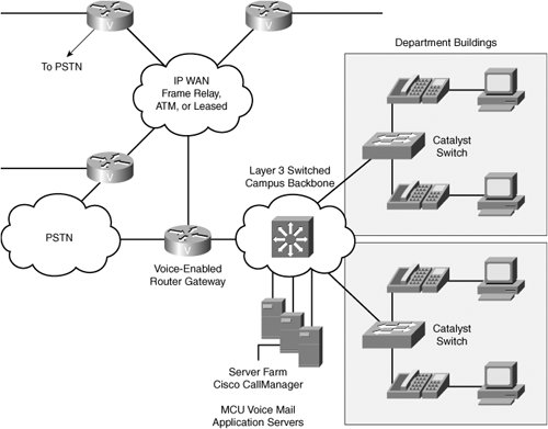 Components for integrated voice and data campus networks, as discussed previously in the "Packet Telephony Components" section, include the following:
When you are designing the campus infrastructure for voice, you must consider the following key issues:
Note Cisco Systems' internal telephone network in San Jose can be considered a campus LAN environment. All desktop phones connect to Ethernet switches and are controlled by Unified CallManager applications. Unified CallManager also controls the gateways and other application servers, such as the Unity server. Enterprise EnvironmentEnterprise networks grow and evolve as company services and locations change and expand. Heavy reliance on information processing and universal access to corporate information has driven network designs to provide reliable access, redundancy, reachability, and manageability. These same principles apply to designing corporation-wide voice access in the enterprise environment. Enterprise networks can be either centralized or distributed call processing environments. In the centralized call processing environment, all of the components of the voice system are controlled by a single centralized call agent, such as Unified CallManager, regardless of their physical location. In a distributed call processing environment, the components of the voice network at each location can act independently. Figure 1-25 depicts an enterprise centralized call processing environment. Centralized voice networks provide enterprise-wide voice access for calls and voice services controlled from a central site. In this environment, the central site provisions all voice services, such as Cisco Unified CallManager, voice mail, and unified messaging. IP phones at remote sites connect to Cisco Unified CallManager through the IP WAN for call processing. Figure 1-25. Enterprise Centralized Call Processing Environment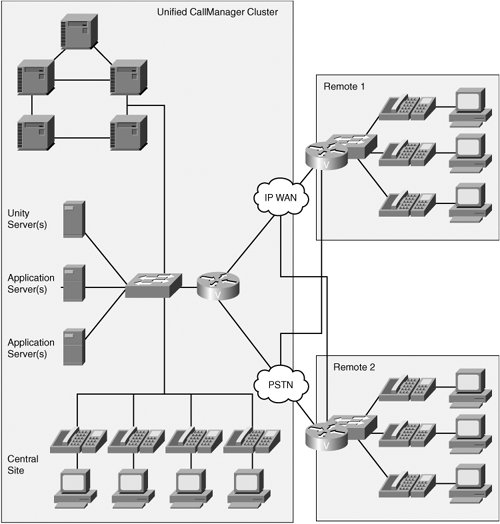 Components for centralized voice enterprise networks include the following:
Figure 1-26 shows an enterprise distributed call processing environment. Distributed voice networks place voice components at each site and utilize the WAN for intersite calls only. Figure 1-26. Enterprise Distributed Call Processing Environment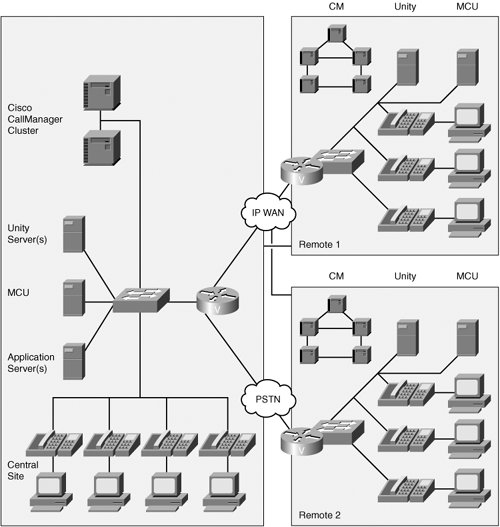 Components for distributed voice enterprise networks include the following:
Modern enterprise network applications include:
Service Provider EnvironmentService provider environments, an example of which is illustrated in Figure 1-27, add another level of complexity to the voice environment. To be competitive, service providers must provide their business customers with more efficient, less expensive alternatives to the PSTN for voice and data services. Figure 1-27. Service Provider Environment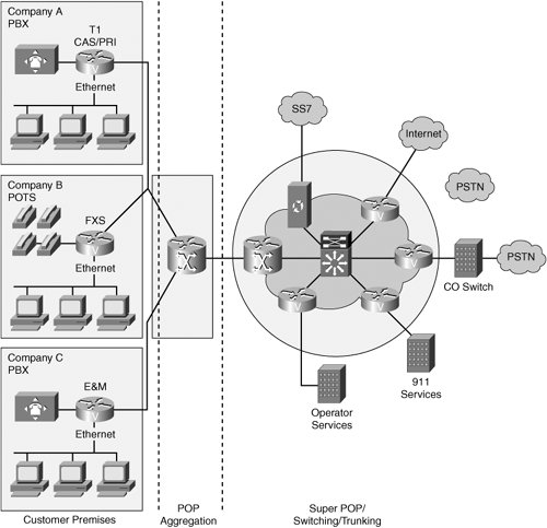 Requirements in the service provider arena include:
|

EAN: 2147483647
Pages: 111