Basic Components of Telephony Networks
| A number of components must be in place for an end-to-end call to succeed. These components are listed here and shown in Figure 1-1:
Figure 1-1. Basic Components of a Telephony Network The next sections describe each of the basic components in more detail. Edge DevicesThe two types of edge devices used in a telephony network include:
Local LoopsA local loop is the interface to the telephone company network. Typically, it is a single pair of wires that carry a single conversation. A home or small business may have multiple local loops. You learn more about local loops in Chapter 2, "Analog and Digital Voice Connections." Private or CO SwitchesThe CO switch terminates the local loop and handles signaling, digit collection, call routing, call setup, and call teardown. You learn more about these switches in the upcoming section "CO Switches and Switching Systems." A PBX switch is a privately owned switch located at the customer site. A PBX typically interfaces with other components to provide additional services, such as voice mail. You learn more about PBXs in the section "Privately Owned Switches" later in this chapter. TrunksThe primary function of a trunk is to provide the path between two switches. There are several common trunk types, as shown in Figure 1-2, including the following:
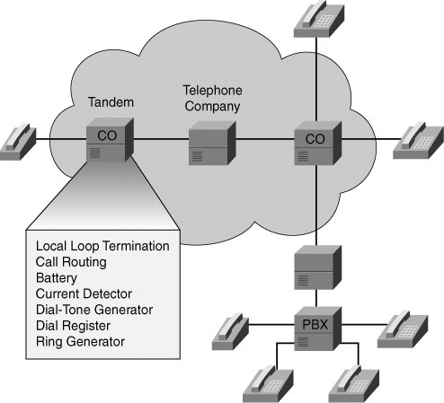
Figure 1-2. Trunk Types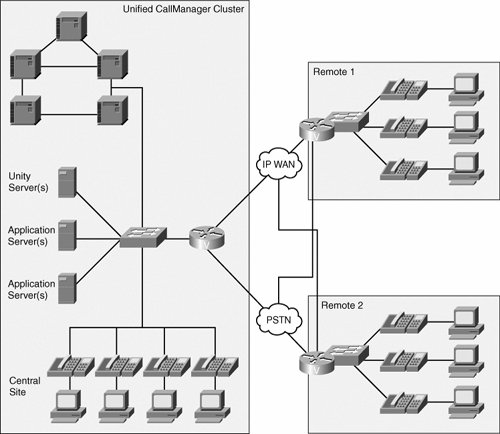 Note The telephone installed in your home is considered an edge device because it terminates the service provided by your local telephone company. The local loop is the pair of wires that come to your house and provide residential telephone service. Trunks are the interconnections between telephone switches. They can be between private switches or telephone company switches. CO Switches and Switching SystemsFigure 1-3 shows a typical CO switch environment. The CO switch terminates the local loop and makes the initial call-routing decision. Figure 1-3. CO Switches The call-routing function forwards the call to one of the following:
The CO switch makes the telephone work with the following components:
Note Some telephones on the market offer additional features that require a supplementary power source that the subscriber supplies; for example, cordless telephones. Some cordless telephones may lose functionality during a power outage. When configuring a PBX connection to a CO switch, the signaling should match that of the CO switch. This configuration ensures that the switch and the PBX can detect on hook, off hook, and dialed digits coming from either direction. Switching systems provide three primary functions:
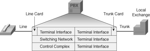
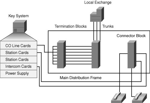
CO switches switch calls between locally terminated telephones. If a call recipient is not locally connected, the CO switch decides where to send the call based on its own call routing information, which is stored in a call-routing table. The call then travels over a trunk to another CO or to an intermediate switch that may belong to an inter-exchange carrier (IXC). Although intermediate switches do not provide dial tone, they act as hubs to connect other switches and provide interswitch call routing. PSTN calls are traditionally circuit-switched, which guarantees end-to-end path and resources. Therefore, as the PSTN sends a call from one switch to another, the same resource is associated with the call until the call is terminated. Note CO switches provide local service to residential telephones. The CO switch provides dial tone, indicating that the switch is ready to receive digits. When you dial your phone, the CO switch receives the digits, then routes your call. The call routing may involve more than one switch as the call progresses through the network. Privately Owned SwitchesIn a corporate environment, where large numbers of staff need access to each other and the outside, individual telephone lines are not economically viable. A PBX is a smaller, privately owned version of the CO switches used by telephone companies, as illustrated in Figure 1-4. Figure 1-4. PBX Most businesses have a PBX telephone system, a key telephone system, or a Centrex service. Large offices with more than 50 telephones or handsets choose a PBX to connect users, both in-house and to the PSTN. PBXs come in a variety of sizes, from 20 to 20,000 stations. The selection of a PBX is important to most companies, because a PBX has a typical life span of seven to ten years. All PBXs offer a standard, basic set of calling features. Optional software provides additional capabilities. A PBX connects to telephone handsets using line cards and to the local exchange using trunk cards. A PBX has three major components:
Call SignalingCall signaling, in its most basic form, is the ability of a device to communicate a need for service to a network. The call-signaling process requires the network to detect a request for service and termination of service, send addressing information, and provide progress reports to the initiating party. This functionality corresponds to the three call-signaling types:
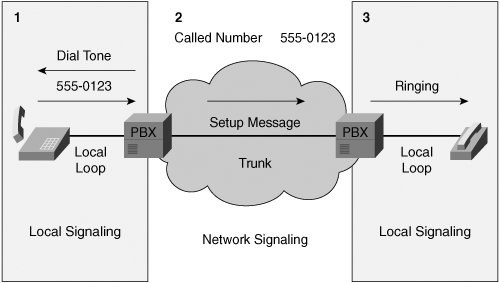
A basic call setup, as illustrated in Figure 1-6, includes supervisory, address, and information signaling components. The supervisory signaling is used, for example, to detect that a phone went off hook. Address signaling occurs when a caller dials digits, and information signaling is represented by the dial tone heard by the caller. Figure 1-6. Basic Call Setup This call setup can be broken down into three major steps. These steps include:
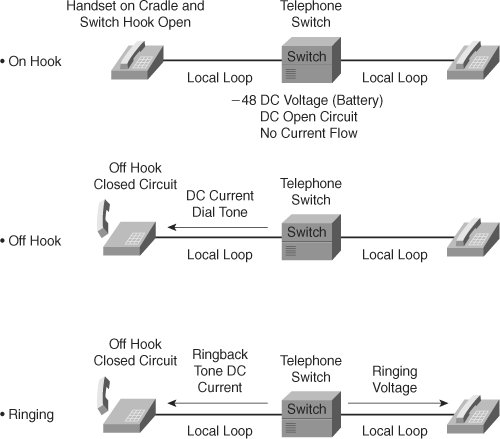
Supervisory SignalingA subscriber and telephone company notify each other of call status with audible tones and an exchange of electrical current. This exchange of information is called supervisory signaling, as shown in Figure 1-7. Figure 1-7. Supervisory Signaling There are three different types of supervisory signaling:
Note The ringing pattern in the United States is 2 seconds of ringing tone followed by 4 seconds of silence. Europe uses a double ring followed by 2 seconds of silence. Address SignalingThere are two types of telephones, as shown in Figure 1-8: a push-button (tone) telephone and a rotary-dial telephone. Figure 1-8. Address Signaling These telephones use two different types of address signaling to notify the telephone company where a subscriber is calling:
Information SignalingTone combinations indicate call progress and are used to notify subscribers of call status. Each combination of tones represents a different event in the call process. These events, whose frequencies and patterns are listed in Table 1-2, include the following:
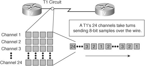
Note A call placed from your residential telephone uses all three types of call signaling. When you lift the handset, a switch in your telephone closes to start current flow and notifies the telephone company that you want to make a call (supervisory signaling). The telephone company then sends dial tone to indicate that it is ready to receive your dialed digits (informational signaling). You then dial your digits by pressing numbers on the keypad (address signaling). Digital versus Analog ConnectionsSupervisory, address, and informational signaling must be carried across both analog and digital connections. Depending on your connection to the network, you must configure specific signaling to match the type of signaling required by the service provider. Figure 1-9 illustrates digital and analog connections coexisting in the same network. Figure 1-9. Address Signaling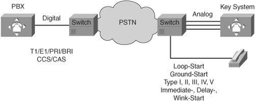 Digital PBX connections to the network are common in many countries. They may be T1 or E1 lines carrying channel associated signaling (CAS) or PRI lines using common channel signaling (CCS). CAS is a signaling method that allows passing on-hook or off-hook status by setting bits that are associated with each specific voice channel. These bits are carried in band for T1 and out of band for E1. An ISDN connection uses the D channel as the common channel to carry signaling messages for all other channels. CCS carries the signaling out of band, meaning that the signaling and the voice path do not share the same channel. Analog interfaces require configuration of a specific signaling type to match the provider requirement. For interfaces that connect to the PSTN or to a telephone or similar edge device, the signaling is configured for either loop start or ground start, the functions of which are discussed in Chapter 2. For analog trunk interfaces that connect two PBXs to each other (that is, E&M interfaces), or a PBX to a CO switch, the signaling is either wink- start, immediate-start, or delay-start, with the signaling type set to 1, 2, 3, 4, or 5. MultiplexingA two-wire analog local loop typically carries one call at a time. To make better use of wiring facilities, different multiplexing techniques have been implemented to enable two-wire or four-wire connections to carry multiple conversations at the same time. Time-division multiplexing (TDM) is used extensively in telephony networks to carry multiple conversations concurrently across a four-wire path, as shown in Figure 1-10. TDM involves simultaneously transmitting multiple separate voice signals over one communications medium by quickly interleaving pieces of each signal, one after another. Information from each data channel is allocated bandwidth based on preassigned timeslots, regardless of whether there is data to transmit. Figure 1-10. Time-Division Multiplexing Frequency-division multiplexing (FDM), as illustrated in Figure 1-11, involves carrying multiple voice signals by allocating an individual frequency range to each call. FDM is typically used in analog connections, although its functionality is similar to that of TDM in digital connections. FDM is used in cable or digital subscriber line (DSL) connections to allow the simultaneous use of multiple channels over the same wire. Figure 1-11. Frequency-Division Multiplexing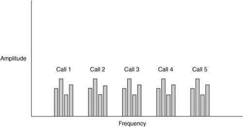 Note If you have cable television service at your home, the television channels are all carried (and multiplexed) over a single pair of wires. This includes both the audio signals and the video signals. All the channels are present on the cable wires all the time. When you select the channel you want to watch, your set-top cable tuner determines which channel is sent to your television. |
EAN: 2147483647
Pages: 111