Chapter 3: Connecting Shapes
|
With Microsoft Office Visio 2003 drawings and diagrams you can communicate all sorts of information about ideas, processes, organizations, layouts, and even buildings. And as you’ve already seen, the basic building blocks you use to create your drawings are the shapes provided on Visio stencils. Connectors are drawing elements that indicate why the shapes are there and what they are doing. Shapes and connectors together give the complete picture. Connected drawings are meaningful drawings.
The previous chapter introduced a few of the methods for connecting shapes. This chapter provides an in-depth look at connectors so that you can revise connected drawings more easily and take advantage of the automated layout features in Visio.
Adding Connectors to Your Diagrams
There are about as many ways to connect shapes in Visio as there are types of Visio drawings. Most drawing types have their own unique visual language, and you’ll find a multitude of connectors and connector behaviors in Visio that are meant to accommodate the needs of each drawing. Visio even includes an entire stencil that contains nothing but connectors.
Despite the variety of connectors, most are nothing more than a line that attaches to one shape at one end and another shape at the other end. For example, in a flowchart, the connector is the line that goes from a process shape to a decision shape, as Figure 3-1 shows. In a network diagram, the connector is the line that connects a printer to a hub. In the first case, the line represents the order in which you do things. In the second case, the line represents an actual network connection. In both cases, the connection tells us something important about the relationship between two shapes. In some drawings, such as database and software model diagrams in Visio Professional, connectors actually trigger the transfer of data between the shapes they are connected to.
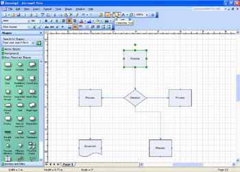
Figure 3-1: Connectors provide additional flexibility in a diagram that lines created with the Line tool don’t.
Using Connectors and the Connector Tool
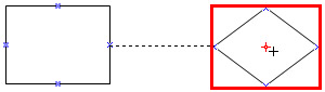
In Visio, the terms connector and 1-D shape are almost synonymous. Whatever term you use, connectors exist so that you can attach lines to 2-D shapes in Visio. To put it simply, a connection happens when you drag an endpoint of a 1-D shape onto a connection point of a 2-D shape. The two ends of a connector aren’t interchangeable—as with any line, there’s a beginning and an end, and Visio stores information about which is which, in essence giving the line directionality.
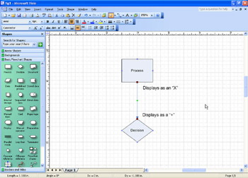
Both 1-D and 2-D shapes provide visual cues that show you where connections can be made (before you connect) and what type of connection has been made (after you connect). On a 2-D shape, each point at which a connection can be made is marked with a connection point, the blue . On a 1-D shape, the ends are marked with square endpoints, which you see when the shape is selected. To help show the direction of the connection, the two endpoints on a 1 D shape are different, as Figure 3-2 shows. The begin point of a 1-D shape has a symbol inside the square. The end point has a + symbol inside the square. Either endpoint can be attached to any connection point on a 2-D shape.
| Tip | If a shape’s connection points aren’t visible, select Connection Points on the View menu. |
Connectors and other types of 1-D shapes are the only shapes that have begin and end points. The begin and end points provide visual feedback that a connection has been established, but they also indicate direction. Think of it this way: if your connector had an arrowhead on it, which way would it point, and why? When you add connectors to a drawing, connect or draw them so that they match the order of your shapes—attach the begin point to the first shape, and attach the end point to the next shape.
Using the Connector Shapes on Stencils
When you start a drawing with a template, Visio opens stencils containing the appropriate shapes and connectors for the drawing type. Many of the basic connector shapes—such as the Dynamic Connector and Line-Curve Connector shapes shown in the stencil in Figure 3-3—appear on multiple stencils to make them easy to find. You can use these shapes in any Visio drawing. Other stencils contain specialized connectors with advanced features and behaviors that support a specific drawing type.
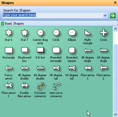
Figure 3-3: Visio includes the Dynamic Connector and Line-Curve Connector master shapes on many stencils, because they work in any drawing type to connect shapes.
Follow these steps to use any connector shape on a stencil:
-
Drag the connector shape from a stencil onto the drawing.
-
Drag an endpoint of the connector to a connection point on a shape.
-
Drag the other end of the connector to a connection point on another shape.
Note New Feature Pause your pointer over a connector shape on a stencil to find out what it does. You can also click the More link in the information box to call up general help on shapes and connectors.
Drawing Connectors with the Connector Tool
The Connector tool works like a drawing tool in that you can select it and then draw connectors between shapes. However, the connections you draw are smarter than plain old lines. Depending on how you position the tool as you drag, you can connect to a specific connection point on the shape or to the whole shape to create a dynamic connector—the same as the shape on a stencil. The difference in how you draw with the Connector tool affects the way you work with shapes afterward, as follows:
-
If you connect to a point, Visio makes sure the connector remains attached to that specific point when you rearrange shapes. This type of connection is called point-to- point or static and is appropriate in electrical wiring schematics, logic diagrams, or any diagram where a specific point has meaning.
-
If you connect to the whole shape, Visio can move the connector to a different point when you rearrange shapes. This type of connection is called shape-to-shape or dynamic and is suitable for workflows, Gantt charts, or other conceptual diagrams.
Follow these steps to use the Connector tool to manually draw connections between shapes:
-
Drag the 2-D shapes you want in your drawing onto the page, and then move them into position.
-
Select the Connector tool on the Standard toolbar, and then create a point-to-point or shape-to-shape connection as follows:
-
For a point-to-point connection, position the Connector tool over a connection point on the first shape. When a red square appears around the point, drag to a connection point on the second shape.
-
For a shape-to-shape connection, position the Connector tool over the center of the first shape until you see a red border around the entire shape. Drag to the center of the second shape.
-
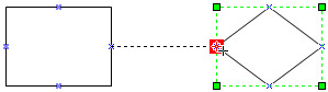
When you release the mouse, Visio displays red handles to show that the shapes are connected. The handles differ in appearance depending on the type of connection, as Figure 3-4 shows.
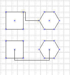
Figure 3-4: The shapes on top have a point-to-point connection. The shapes on the bottom have a shape-to-shape connection.
Drawing Specific Connectors with the Connector Tool
With the addition of one step, you can use the Connector tool to create any sort of connector that appears on a stencil. By default, when you connect shapes using the Connector tool, you create a dynamic connector. However, you can use the Connector tool in tandem with a connector shape on a stencil to draw that shape instead.
Follow these steps to use the Connector tool to draw a different connector type:
-
Drag the 2-D shapes you want in your drawing onto the page, and then move them into position.
-
Select the Connector tool on the Standard toolbar.
-
Click once on a connector master shape in the stencil window. For example, click the Line-Curve Connector shape.
-
On the drawing page, draw a connector from shape to shape as described in the previous procedure.
The tool draws the type of connector you selected on the stencil instead of the default dynamic connector.
Tip As long as the Connector tool remains selected on the Standard toolbar, shapes you drag from the stencil to the drawing page will be connected automatically.
Changing the Type of Connection
If you need to change the point to which a connector is attached or change the type of connection altogether, you can do this by disconnecting and reconnecting shapes: simply drag the glued endpoint slightly away from the shape to disconnect it, and then drag the endpoint back over the shape’s center to reattach as a shape-to-shape connection or to a particular connection point to reattach as a point-to-point connection.
| Tip | Create a shape-to-shape connection One way to ensure that you’re creating a shape-to-shape connection is to hold down the Ctrl key as you drag an endpoint (or the Connector tool) over a shape. This technique is handy for connecting shapes that are small or complex or for shapes that have a connection point in the center area. |
Shapes won’t stay connected, and the handles don’t turn red
The basic technique for connecting shapes is to drag the endpoint of a connector to a connection point on a 2-D shape. Dragging the entire connector or line might result in a connection if the endpoint comes near a connection point. However, dragging a 2-D shape over to the connector won’t work. Some shapes that look like connectors are really 2-D shapes. Make sure you’re using a 1-D shape with a begin point and an end point as a connector.
| Note | You might notice that the Stamp tool, which is used to duplicate images on your page, has been removed from the Connector drop-down menu. You can display it by clicking Toolbar Options, Add Stamp Tool. |
Dragging Connectors from Shapes
Some shapes include a connector built into the shape, such as the Ethernet shape in a network diagram and the tree shape shown in Figure 3-5. You can drag a control handle on the shape to pull a connector directly out of the shape and attach it to another shape. With these shapes, you can move only one end of the connector; the other end is already attached to the shape.
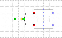
Figure 3-5: Some shapes, such as the Multi-Tree Sloped shape on the Blocks stencil, have control handles with connectors that you can attach to other shapes.
Control handle tips
Control handles are your clue that a shape does something special—but you generally can’t tell what that is just by the shape’s appearance. A control handle might configure a curve, reposition a text block or other component, or associate a shape with another shape. When you see a control handle, pause your pointer over it to display a ScreenTip about what it does.
Connecting a Series of Shapes All at Once
When you want to create shape-to-shape connections throughout a diagram, let Visio connect shapes for you. You can use the following technique for enormous layout flexibility, because it works well with the automated tools described in the next section. To connect a series of shapes, select them one by one in the order you wish to connect them. For example, select shapes from top to bottom or from start to finish. Once the shapes are selected, choose Shapes, Connect Shapes.
|
EAN: 2147483647
Pages: 209
- ERP Systems Impact on Organizations
- Challenging the Unpredictable: Changeable Order Management Systems
- Enterprise Application Integration: New Solutions for a Solved Problem or a Challenging Research Field?
- Healthcare Information: From Administrative to Practice Databases
- Relevance and Micro-Relevance for the Professional as Determinants of IT-Diffusion and IT-Use in Healthcare