Chapter 17: Using CAD Drawings in Visio
|
You’re designing a sound system or a conference room layout or some ductwork—something that you know Microsoft Office Visio 2003 can do—and you want to include an existing CAD drawing from the architect or engineer. Why start from scratch? Visio does a good job of importing CAD drawings as background images that you can annotate with Visio shapes. You can even convert CAD objects to Visio shapes when you want to edit more extensively. In addition, you can convert Visio drawings to CAD-readable format. Visio includes filters and converters for both Autodesk AutoCAD DWG and DFX formats, IntelliCAD DWG format, and Bentley MicroStation DGN format. In Visio 2003 the improved DWG converter assures that the drawings converted to Visio have higher fidelity than the original CAD files, allowing you to work with even more accuracy than before.
In case you are new to the concept, let us explain. CAD refers to a variety of specialized drawing programs capable of producing highly detailed, accurate drawings, such as for machined parts or construction. Obviously, Visio’s strengths differ from those of a CAD program. Whether you know much about CAD programs or not, this chapter provides the information you need to help you get the best results when you’re working with CAD files in Visio drawings.
How Visio Works with CAD Programs
Experienced CAD users might come to Visio with expectations that Visio can’t meet. Visio was never intended to be a substitute for high-end drafting and design tools. However, many people work with drafters, engineers, and architects and simply want the benefit of working with their drawings—without taking a CAD class first. That’s where Visio can help. Visio provides several methods of bringing CAD files into a Visio document or using Visio diagrams in a CAD program. You can do the following:
-
Import a CAD drawing for display only. Visio online Help refers to this as “inserting” a CAD drawing. Visio displays a copy of the CAD drawing as an OLE embedded object that you can use as a background page, reference layer, or detailed insert, but you can’t edit its contents.
-
Convert a CAD drawing, which converts the original objects to fully editable Visio shapes.
-
Export a Visio diagram as a DWG, DXF, or DGN file. In a multiple-page Visio diagram, you must export each page separately.
Most of the time, when you need to display a CAD drawing in Visio, your best option is to insert it as a display-only object rather than convert it, as Figure 17-1 shows. You can use the display-only CAD image as a background layer so that you can enter comments or drag Visio shapes on top of it, or you can insert the CAD drawing onto the page and crop it to provide detail for a portion of your Visio drawing.
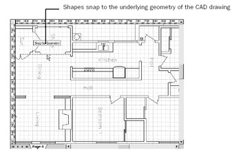
Figure 17-1: An inserted CAD floor plan provides an accurate backdrop for electrical, HVAC, network, or other shapes, which you can drop on top.
| Warning | CAD drawings are often large files and importing them into a drawing may make Visio respond sluggishly on slower computers. |
| Cross-Reference | For details about background pages in Visio, see “Using Background Pages,” page 51. |
For occasions when you really need to edit the geometry of a CAD object within Visio, you can convert a drawing. For example, maybe you have a legacy CAD file that you need to revise, but no access to the program used to create it. By converting the CAD objects to Visio shapes, you gain full control of the file. You can also convert in the other direction— converting a Visio diagram into a CAD-readable format. However, no one at Microsoft recommends round-tripping Visio and CAD files. Consider the two conversion features to be one-way only.
| Note | The ability to insert CAD drawings in Visio files is included with both Visio Standard and Visio Professional. |
Using Visio for CAD Users
If you’re used to working in a CAD program, you’ll notice that Visio products use a different approach to drawing. For starters, Visio uses a drawing page instead of model space, and you create shapes with masters rather than blocks. Several other tasks you perform in CAD programs are also accomplished differently in Visio as the following sections describe.
Model Space Versus the Drawing Page
In CAD programs, you create a model in the coordinate system referred to as model space. If you display a model in a view port, the coordinate system is transformed to paper space, so you can print or plot the diagram.
In Visio, however, you begin and end your work on the drawing page. In CAD terms, you can think of the Visio drawing page as a single, two-dimensional view port into model space. Visio shapes are vectors for which dimensions are measured as width and height. A shape’s location is its position on the plane represented by the drawing page. The coordinates on the drawing page are measured in units that correspond with the real-world measurement units of the object or space you’re representing, as Figure 17-2 shows. For example, if you’re drawing a floor plan, the Visio ruler might show that the drawing page is 100 feet (ft.) wide, but in reality, the drawing page prints on a standard paper size, such as D-size plotter paper.
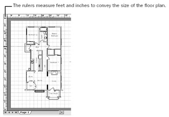
Figure 17-2: On the Visio drawing page, coordinates are measured in units that correspond with the actual size of the represented objects.
The last view in which a CAD drawing was saved before you bring it into Visio affects how it looks and what you can do with it in Visio. In general, you’ll get better results if the CAD drawing is saved in model space. This is especially true if you’re converting the drawing and its contents to shapes. Visio can convert all the objects and text from the specified layers of a drawing saved in model space. If the drawing was saved in paper space, Visio converts objects and text quite literally as they appear—but at least they’re converted. For example, if an object or text in paper space appears to be clipped at the edge of the view port, the clipping is converted to Visio lines, rather than the whole object represented by the clipped portion.
In addition, if a CAD drawing was last saved in paper space, you won’t be able to change its drawing scale when you insert or convert it.
World Coordinates Versus Drawing Units
In CAD programs, you draw in the real-world units of the world coordinate system. In Visio, you draw in drawing units, which can be any units you specify. In addition, you usually specify a drawing scale in Visio before you start to draw. A drawing scale is the ratio of space on the page to real-world measurement units. In a floor plan, for example, it’s impractical (to say the least) to print a page that is 40 ft. wide. But if you specify a drawing scale of 1/4 in. = 1 ft., you can represent a building that’s 40 ft. wide on standard letter-sized paper.
| Note | For details about drawing scales and units of measure in Visio, see “Setting Up Measurements in a Diagram,” page 421. |
When you insert or convert a CAD drawing, Visio sets a custom drawing scale that ensures the CAD drawing will fit on the Visio drawing page. If the CAD drawing is large, and the Visio drawing page is small, the result is a new drawing scale that forces the CAD drawing to fit—which might not be the ideal drawing scale for your purpose. You can, however, control the drawing scale and the page size either when you insert or convert the drawing, or later after it’s in Visio.
Visio Equivalents for CAD Commands
If you’re used to working in a CAD program, you might find Visio terminology confusing. Some of the commands common to CAD programs aren’t available in Visio at all; others are a little different and might even be easier to use in Visio. Table 17-1 summarizes commands and tasks that are commonly available in CAD programs and the equivalent functionality in Visio.
| Task in a CAD Program | Technique in Visio |
|---|---|
| Set the drawing scale | Choose File, Page Setup, click the Drawing Scale tab, and then select a scale. In Visio, set the drawing scale before you begin to work. For details, see “Setting Up Measurements in a Diagram,” page 421. |
| Move an object | Select a shape with the Pointer tool and drag it. Or choose View, Size & Position Window to open a window in which you can specify a new shape position. |
| Move an object a specific distance | Use the Size & Position window. If you have Visio Professional, you can use the Move Shapes add-in (choose Tools, Add-Ons, Visio Extras, Move Shapes). For details, see “Moving Shapes with the Move Shapes Add-In,” page 441. |
| Copy an object | Select a shape, and then hold the Ctrl key while you drag a copy to a new location. Or use the standard Windows shortcuts—Ctrl+C and Ctrl+V—to copy and paste objects. |
| Create a block or a cell | Use the Visio drawing tools to create a shape, and then drag the shape to a stencil to create a master shape. |
| Pan and zoom a drawing | Choose View, Pan & Zoom Window to open a window in which you can adjust the view of a drawing. |
| Use operations such as Union, Fragment, and Join to create objects | Choose Shape, Operations, and then choose an action. For details, see “Merging Shapes to Create New Ones,” page 660. |
| Add a hatch pattern to an object | Select a shape, and then choose Format, Fill. You can set the color, pattern, and pattern color for the hatch. You can also create your own patterns. See “Creating Your Own Line and Fill Patterns,” page 693. |
| Use entity snaps or object snaps | Choose Tools, Snap & Glue, and select the Shape Extensions option. On the Advanced tab, select the shape extensions you want to use. |
Drawings with Externally Referenced or Image Files
If you import or convert a CAD drawing that includes xref commands, Visio looks for the referenced files and displays a message if it can’t find them. You can avoid seeing the warning message about externally referenced files in one of two ways: either create the same folder hierarchy on your computer, or place all externally referenced files in the same folder as the Visio drawing.
In addition, if you import a DWG file that includes embedded image files, Visio can display them—but not until you convert the CAD drawing. The image files won’t appear when you import the file, but if you convert the drawing to Visio shapes, any image files included will appear.
|
EAN: 2147483647
Pages: 209