Topologies
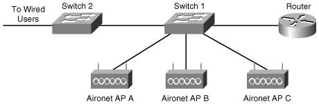
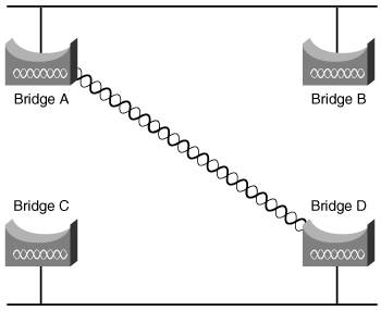
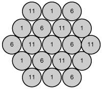
| If you had occasion to design a wired LAN, you know the issues involved when you design the topology of that network. You need to strike a balance to provide both the services and the throughput users need. With a WLAN, not only must you take the issues involved in a wireless network to heart, but you must also add the considerations of an 802.11 deployment. After you design the physical topology, you must decide which wireless channels to use, along with their placement throughout your organization. WLAN TopologiesThere are two basic topology designs involved in a WLAN: ad hoc and infrastructure. You are more apt to see and use an infrastructure topology in your WLAN deployments, but it's useful to understand ad hoc and how it could be used in your own organization. Ad HocThe most elementary topology is known as an ad-hoc topology. In this design, two or more devices link together, without the need for an AP. This sort of topology is useful not only when coworkers meet in a remote location and want to share files, but also in environments in which networking is desired, but in which you cannot run cabling. For example, disaster workers don't have time to set up network infrastructure when they show up on scene. The downside to an ad-hoc topology is that users do not have access to the network and its resources. Ad-hoc networks are also difficult to troubleshoot. You cannot check the association status of all clients as you can with an AP. InfrastructureThe more common type of topology that allows access to wired network resources is the infrastructure topology. In this topology, APs are added to a switch, which provides connectivity to wireless stations. Figure 7-3 shows an example of an infrastructure topology. Figure 7-3. Infrastructure Topology In this example, an AP backbone is added to the rest of the wired network. Bridge TopologiesTypically, you can connect two devices to link bridges or you can link one bridge to multiple bridges. However, there's another topology you might consider when you deploy your own bridging solution. The spanning-tree topology provides path redundancy and prevents network loops. When you use the spanning-tree algorithm, a loop-free path is computed within a layer 2 network. Bridges and switches send and receive regular bridge protocol data units (BPDU). These messages are used to construct a loop-free path. A loop in a network can cause duplicate messages and network instability. Spanning-tree blocks redundant paths. If a network segment in the spanning-tree fails, the spanning-tree algorithm calculates the spanning-tree topology and activates the next path. Figure 7-4 shows an example of the spanning-tree topology. In this example, Bridge D is elected as the spanning-tree root, which is the central bridge in the spanning-tree topology. This is because it was given a higher priority than the other bridges. Figure 7-4. Spanning-Tree Topology Note If all the bridges have the same priority, the bridge with the lowest MAC address is elected as the spanning-tree root. Channel SetupWhen you think about an AP's range, you might think that "farther is better." That's not necessarily true. In some cases you might want a shorter range so that you can reuse channels. Also, a smaller cell size allows fewer users per AP, so you wind up with greater throughput. In a station-dense part of your organization, you can have three APs, each operating on a nonoverlapping channel. In the United States, the 802.11b and 802.11g spectrum is divided into 11 channels. Ideally, when you place cells next to one another, you want neighboring cells at least five channels apart. Figure 7-5 shows a cellular layout that uses channels 1, 6, and 11. Figure 7-5. Channel Layout for Multiple Cells Channel layout is easy enough to do on paper, but reality is harder. You have to factor in the real range afforded by your environment, as well as the realities of a three-dimensional world. An AP on channel 6 on the third floor might interfere with an AP on channel 6 on the second floor. Note One way to avoid channel overlapping with 802.11b and 802.11g is to use an 802.11a solution. 802.11a offers 23 nonoverlapping channels. If you add 802.11a cells it's a little easier, because you can choose from more channels, and they don't overlap as much as 802.11b and 802.11g cells. |
EAN: 2147483647
Pages: 126