Storage Improvements
Let’s begin by examining some of the storage improvements found in Windows Server 2008. We’ll key in on and briefly describe the following features:
-
File Server role
-
Windows Server Backup
-
Storage Explorer
-
SMB 2.0
-
Multipath I/O (MPIO)
-
iSCSI Initiator
-
Remote Boot
-
iSNS Server
File Server Role
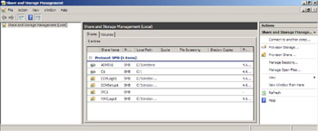
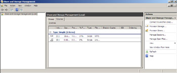
As we saw previously in Chapter 5, “Managing Server Roles,” one of the roles you can add to a Windows Server 2008 server is the File Server role. And as we also saw in Chapter 5, when you add this particular role, there are also several optional role services you can install on your machine. Beta 3 of Windows Server 2008 includes a new tool for managing the File Server role-namely, the Share And Storage Management MMC snap-in. This new snap-in presents a unified overview of the File Server resources within a given system, including separate tabs for shared directories and storage volumes, and two new provisioning wizards that are designed to assist you in configuring shares and storage for the File Server role. The main console of the Share And Storage Management snap-in displays a tabbed overview of shares and volumes with key properties, and it exposes the following management actions:
-
Volume actions: extend, format, delete, and configure properties
-
Share actions: stop sharing and configure properties
Let’s look at a few screen shots of this new snap-in. First, here’s the Share And Storage Management node selected with the focus on the Shares tab, which shows all the shared folders managed by the server:
And here’s the same snap-in with the focus on the Volumes tab:
The Share And Storage Management snap-in also provides you with two easy-to-use wizards for managing your file server: the Provision A Shared Folder Wizard and the Provision Storage Wizard.
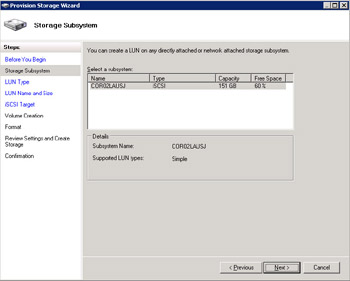
The Provision Storage Wizard provides an integrated storage provisioning experience for performing tasks such as creating a new LUN, specifying a LUN type, unmasking a LUN, and creating and formatting a volume. The wizard supports multiple protocols, including Fibre Channel, iSCSI, and SAS, and it requires a VDS 1.1 hardware provider. Here’s a screen shot showing the Provision Storage Wizard and displaying on the left the various steps involved in running the wizard:
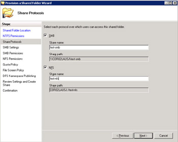
The Provision A Shared Folder Wizard provides an integrated file share provisioning experience that lets you easily select sharing protocols (SMB or NFS). Depending on your protocol selection, the wizard lets you configure either SMB or NFS settings. The following SMB settings can be configured:
-
User limit
-
Access-based enumeration
-
Offline settings
-
NTFS and share permissions
Or you can specify NFS settings such as these:
-
Allow anonymous access
-
Client groups and host permissions
In addition, the wizard lets you specify a quota or file screen template and add or publish your share to a DFS namespace. Here’s a screen shot showing the Provision A Shared Folder Wizard and displaying on the left the various steps involved in running the wizard:
Windows Server Backup
Windows Server Backup is the replacement for the NTBackup.exe tool found on previous versions of Windows Server. It’s implemented as an optional feature you can install using Server Manager, the Initial Configuration Tasks screen, or the ServerManagerCmd.exe command. Windows Server Backup uses the Volume Shadow Copy Service first included in Windows Server 2003. Because of this, Windows Server Backup takes a snapshot of any volume and backs the volume up without having to take the server down because of applications or services that are running. The result of this is that you no longer need to worry about scheduling backups during downtimes when the system is idle.
Windows Server Backup was basically designed to target the single-server backup needs for DIYs (do-it-yourselfers) because most small organizations don’t bother to back up until a disaster strikes. Additionally, Microsoft studies revealed that the NTBackup.exe tool found in previous versions of Windows Server was generally too complex for this market segment to use effectively. Windows Server Backup is not targeted toward typical mid- and large-sized organizations, as they typically use third-party backup solutions from vendors.
In a nutshell, here’s what Windows Server Backup is all about: Windows Server Backup is an in-box backup and recovery tool in Windows Server 2008 that protects files, folders, volumes, application data, and operating system components. It provides recovery granularity for everything from full servers to data pertaining to individual files or folders, applications, or system state information. It is not, however, intended as a feature-by-feature replacement for NTBackup.exe. The focus of the tool’s design is simplicity, reliability, and performance so that the IT generalist can use it effectively. The tool has minimal configuration requirements and provides a wizard-driven backup/recovery experience. Figure 12-1 shows the new Windows Server Backup MMC snap-in, which can be used to perform either scheduled or ad hoc backups on your server.
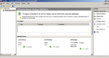
Figure 12-1: Windows Server Backup MMC snap-in
Windows Server Backup uses the same block-level image-based backup technology that is used by the CompletePC Backup And Recovery feature in Windows Vista. In other words, Windows Server Backup backs up volumes using the Microsoft Virtual Server .vhd image file format just like CompletePC does on Windows Vista. Using snapshots on the target disk optimizes space and allows for instant access to previous backups when needed, and block-level recovery can be used to restore a full volume and for bare-metal restore (BMR). This improved bare-metal restore (which builds on the ASR of NTBackup.exe in Windows Server 2003) means also that no floppy disk is needed anymore to store disk configuration information. In addition, you can perform recovery from the Windows Recovery Environment (WinRE) using single-step restore, where only one reboot is required. You can also mount a snapshot of a .vhd file as a volume for performing file, folder, and application data recovery. Note that Windows Server Backup takes only one full snapshot of your volume-after that it’s just differentials that are captured.
An important point is that Windows Server Backup is optimized for backing up to disk, not tape. You can also use it for backing up servers to network shares or DVD sets, but there is no tape support included. Why is that? Well, just consider some of the trends occurring in today’s storage market that are beginning to drive new backup practices. For example, one strong trend is the movement toward disk-based archival storage solutions. The cost of disk storage capacity was originally around ten times the cost of tape, but with massive consumer adoption of small form-factor devices that include hard drives in them, the cost of disk storage capacity has dropped precipitously to about twice the cost of tape. As a result, many admins are now implementing “disk to disk to tape” backup solutions, which leverage the low latency of disk drives to provide fast recoveries when needed. And with Windows Server Backup on Windows Server 2008, an admin can quickly mount a local (SATA, USB, or FireWire) disk or a SAN (iSCSI or FC) disk and seamlessly schedule regular backup operations.
Finally, Windows Server Backup also includes a command-line utility, Wbadmin.exe, that can be used to perform backups and restores from the command line or using batch files or scripts. Here’s a quick of example of how you can use this new tool. Say that you’re the administrator of a mid-sized company with a dozen or so Windows Server 2008 servers that you need to have backed up regularly. Instead of purchasing a backup solution from a third-party ISV, you decide to use the Wbadmin.exe tool to build your own customized backup solution. You’ve installed the Windows Server Backup feature on all your servers, and they have backup disks attached. You want to ensure that the C and E drives on your servers are being backed up daily at 9:00 PM. Here’s a command you can run to schedule such backups:
Wbadmin get disks Wbadmin enable backup –addtarget:<disk identifier> -schedule:21:00 –include:c:,e:
Say that you then get a call from one of your users informing you that some important documents were accidentally deleted from d:\users\tallen\business and need to be recovered. You can try recovering these documents from the previous evening’s backup by doing this:
Wbadmin get versions Wbadmin start recovery –version:<version-id> -itemtype:file –items: d:\users\tallen\business –recursive Wbadmin start recovery –version:<version-id> -itemtype:file –items: d:\users\tallen\business –recoverytarget: d:\AlternatePath\ -recursive
What if a server failed and you had to do a bare-metal recovery? To do this, just use the Windows Server 2008 media to boot in to the WinRE environment and choose the option to perform a recovery of your entire server from the backup hard disk onto the current hard disk. To do this, once you’re in the WinRE environment, launch a command prompt and type this:
Wbadmin get versions –backuptarget:<drive-letter> Wbadmin start BMR –version:<version-id> -backuptarget:<drive-letter> - restoreAllVolumes –recreateDisks
Finally, for those of you who are still not convinced that Windows Server Backup is better than the NTBackup.exe tool in the previous platform (and I know you’re out there somewhere, griping about “No tape support”), Table 12-1 provides a comparison of features for the two tools. Guess which one has the most supported features?
| Feature | NT Backup | Server Backup |
|---|---|---|
| User Data Protection | Yes | Yes |
| System State Protection | Yes | Yes |
| Disaster Recovery Protection | Yes | Yes |
| Application Data Protection | No | Yes |
| Disk Media (not VTL) Storage | Yes | Yes |
| DVD Media Storage | No | Yes |
| File Server Storage | Yes | Yes |
| Tape Media Storage | Yes | No |
| Remote Administration | No | Yes |
Storage Explorer
Storage Manager for SANs (SMfS) was available in Windows Server 2003 R2 as a tool to help you create and manage logical unit numbers (LUNs) on Fibre Channel (FC) and iSCSI disk drive subsystems that support the Virtual Disk Service (VDS) in your storage area network (SAN). Windows Server 2008 builds on this by providing a new tool called Storage Explorer, an MMC snap-in that provides a tree-structured view of detailed information concerning the topology of your SAN.
Storage Explorer uses industry-standard APIs to gather information about storage devices in FC and iSCSI SANs. With Storage Explorer, the learning curve for Windows admins is much easier than traditional proprietary SAN management tools because it is implemented as an MMC snap-in and therefore looks and behaves like applications that Windows admins are already familiar with. The Storage Explorer GUI provides a tree-structured view of all the components within the SAN, including Fabrics, Platforms, Storage Devices, and LUNs. Storage Explorer Management also provides access to the TCP/IP management interfaces of individual devices from a single GUI. By combining Storage Explorer and SMfS, you get a full-featured SAN configuration management system that is built into the Windows Server 2008 operating system.
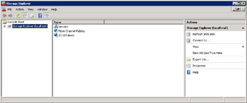
Let’s now take a look at a few screen shots showing Storage Explorer at work. First, here’s a shot of the overall tree-structured view showing the components of the SAN, that is Windows servers, FC Fabrics, and iSCSI Fabrics:
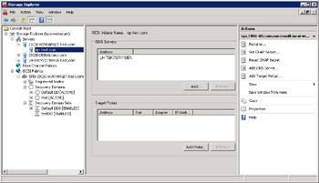
Let’s drill down into each of these three subnodes. Here’s a shot of the Servers node showing various servers (these shots were taken using internal test servers at Microsoft, so their names have been obfuscated):
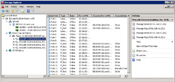
And here’s a screen capture displaying details under the Fibre Channel Fabrics subnode:
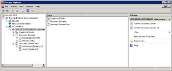
Finally, this one shows details under the iSCSI Fabrics subnode:
SMB 2.0
Another enhancement in Windows Server 2008 (and in Windows Vista) is version 2 of the Server Message Block (SMB) protocol. SMB is used by client computers to request file services from servers over a network. SMB is also used as a transport protocol for remote procedure calls (RPCs) because it supports the creation and use of named pipes. Unfortunately, SMB 1.0 on previous Windows platforms is considered overly “chatty” as a protocol-that is, it generates too much network traffic, especially for use over slow or congested WAN links. In addition, SMB 1.0 has some restrictive constants regarding the number of open files and the total number of shares it can support and it doesn’t support durable handles or symbolic links. Finally, the signing algorithms used by SMB 1.0 are cumbersome to use.
As a result of these considerations, Microsoft introduced SMB 2.0 in Windows Vista and includes support for this protocol in Windows Server 2008. The benefits of the new protocol include less restrictive constants for file sharing, packet compounding to reduce chattiness, improved message signing, and support for durable handles and symbolic links.
Note that Windows Server 2008 and Windows Vista support both SMB 1.0 and SMB 2.0. The version of SMB that is used in a particular file-sharing scenario is determined during the SMB session negotiation between the client and the server, and it also depends on the operating system on the client and server as well-see Table 12-2 for details.
| Client | Server | Version of SMB used |
|---|---|---|
| Windows Server 2008 or Windows Vista | Windows Server 2008 or Windows Vista | SMB 2.0 |
| Windows Server 2008 or Windows Vista | Windows XP, Windows Server 2003, or Windows 2000 | SMB 1.0 |
| Windows XP, Windows Server 2003, or Windows 2000 | Windows Server 2008 or Windows Vista | SMB 1.0 |
| Windows XP, Windows Server 2003, or Windows 2000 | Windows XP, Windows Server 2003, or Windows 2000 | SMB 1.0 |
Multipath I/O
When you think of high-availability storage for your organization, you might think of using RAID to provide disk redundancy and fault tolerance. Although this is a good solution, it protects only your disks. Also, if there’s only one path from your server to your storage device and any component in that path fails, your data will be unavailable-no matter how much disk redundancy you’ve implemented.
A different approach to providing high-availability storage is to use multipathing. A multipathing (or multipath I/O) solution is designed to provide failover using redundant physical path components, such as adapters, cables, or switches that reside on the path between your server and your storage device. If you implement a multipath I/O (MPIO) solution and then any component fails, applications running on your server will still be able to access data from your storage device. In addition to providing fault tolerance, MPIO solutions can also load-balance reads and writes among multiple paths between your server and your storage device to help eliminate bottlenecks that might occur.
MPIO is basically a set of multipathing drivers developed by Microsoft that enables software and hardware vendors to develop multipathing solutions that work effectively with solutions built using Windows Server 2008 and vendor-supplied storage hardware devices. Support for MPIO is integrated into Windows Server 2008 and can be installed by adding it as an optional feature using Server Manager. To learn more about MPIO support in Windows Server 2008, let’s hear now from a couple of our experts at Microsoft:
Windows Server 2008 includes many enhancements for the connectivity of Windows Server servers to SAN devices. One of these enhancements, which enables high availability for connecting Windows Server servers to SANs, is integrated Microsoft MPIO support. The Microsoft MPIO architecture supports iSCSI, Fibre Channel, and Serial Attached SCSI (SAS) SAN connectivity by establishing multiple sessions and connections to the storage array. Multipathing solutions use redundant physical path components-adapters, cables, and switches-to create logical paths between the server and the storage device. If one or more of these components fail and cause the path to fail, multipathing logic uses an alternate path for I/O so that applications can still access their data. Each NIC (in the case of iSCSI) or host bus adapter (HBA) should be connected through redundant switch infrastructures to provide continued access to storage in the event of a failure in a storage fabric component. Failover times will vary by storage vendor and can be configured through timers in the parameter settings for the Microsoft iSCSI Software Initiator driver, the Fibre Channel host bus adapter driver, or both.
New Microsoft MPIO features in Windows Server 2008 include a native Device Specific Module (DSM) designed to work with storage arrays that support the Asymmetric logical unit access (ALUA) controller model (as defined in SPC-3) as well as storage arrays that follow the Active/Active controller model. The Microsoft DSM provides the following load balancing policies (note that load balancing policies are generally dependent on the controller model-ALUA or true Active/Active-of the storage array attached to Windows):
-
Failover No load balancing is performed. The application will specify a primary path and a set of standby paths. Primary path is used for processing device requests. If the primary path fails, one of the standby paths will be used. Standby paths must be listed in decreasing order of preference (that is, most preferred path first).
-
Failback Failback is the ability to dedicate I/O to a designated preferred path whenever it is operational. If the preferred path fails, I/O will be directed to an alternate path until but will automatically switch back to the preferred path when it becomes operational again.
-
Round Robin The DSM will use all available paths for I/O in a balanced, round robin fashion.
-
Round Robin with a Subset of Paths The application will specify a set of paths to be use in Round Robin fashion, and a set of standby paths. The DSM will use paths from primary pool of paths for processing requests as long as at least one of the paths is available. The DSM will use a standby path only when all the primary paths fail. Standby paths must be listed in decreasing order of preference (that is, most preferred path first). If one or more of the primary paths become available, DSM will start using the standby paths in their order of preference. For example, given 4 paths–A, B, C, and D, A, B, and C are listed as primary paths and D is standby path. The DSM will choose a path from A, B, and C in round robin fashion as long as at least one of them is available. If all three fail, the DSM will start using D, the standby path. If A, B, or C become available, DSM will stop using D and switch to the available paths among A, B, and C.
-
Dynamic Least Queue Depth The DSM will route I/O to the path with the least number of outstanding requests.
-
Weighted Path Application will assign weights to each path; the weight indicates the relative priority of a given path. The larger the number the lower the priority. The DSM will choose a path, among the available paths, with least weight.
The Microsoft DSM remembers Load Balance settings across reboots. When no policy has been set by a management application, the default policy that will be used by the DSM will be either Round Robin, when the storage controller follows the true Active-Active model, or simple Failover in the case of storage controllers that support the SPC-3 ALUA model. In the case of simple Failover, any one of the available paths could be used as primary path, and the remaining paths will be used as standby paths.
Microsoft MPIO was designed specifically to work with the Microsoft Windows operating system, and Microsoft MPIO solutions are tested and qualified by Microsoft for compatibility and reliability with Windows. Many customers require that Microsoft support their storage solutions, including multipathing. With a Microsoft MPIO-based solution, customers will be supported by Microsoft should they experience a problem. For non-Microsoft MPIO multipathing implementations, Microsoft support is limited to best-effort support only, and customers will be asked to contact their multi-path solution provider for assistance. Customers should contact their storage vendor to obtain multipathing solutions based on Microsoft MPIO.
Microsoft MPIO solutions are also available for Windows Server 2003 and Windows 2000 Server as a separately installed component.
Adding MPIO Support
To install MPIO support on a Windows Server 2008 server, do the following:
-
Add the Microsoft MPIO optional feature by selecting the Add Features option from Server Manager.
-
Select Multipath I/O.
-
Click Install.
-
Allow MS MPIO installation to complete and initialize.
-
Click Finish.
Configuration and DSM Installation
Additional connections through Microsoft MPIO can be configured through the GUI configuration tool or the command-line interface. MPIO configuration can be launched from the control panel (classic view) or from Administrative Tools.
Adding Third-Party Device-Specific Modules
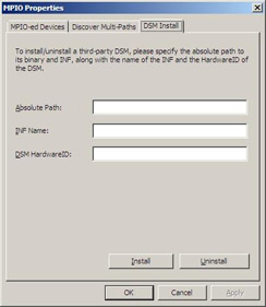
Typically, storage arrays that are Active/Active and SPC3 compliant also work using the Microsoft MPIO Universal DSM. Some storage array vendors provide their own DSMs to use with the Microsoft MPIO architecture. These DSMs should be installed using the DSM Install tab in the MPIO properties Control Panel configuration utility:
–Suzanne Morgan
Senior Program Manager, Windows Core OS
–Emily Langworthy
Support Engineer, Microsoft Support Team
iSCSI Initiator
iSCSI, which stands for Internet Small Computer System Interface, is an interconnect protocol based on open standards that is used for establishing and managing connections between TCP/IP-based storage devices, servers, and clients. iSCSI was designed as an alternative to Fibre Channel (FC) for deploying SANs, and it supports the block-based storage needs of database applications. Advantages of iSCSI over FC include lower cost and a more flexible topology, the ease of scaling up (more devices) and across (devices from different vendors), and virtual lack of inherent distance limitations on the protocol’s operations.
Although the need for SANs in large enterprises continues to grow, organizations often find them difficult and expensive to implement or become locked into a single storage vendor’s solution. By contrast, iSCSI SANs are easier to implement and can leverage your existing TCP/IP networking LAN/WAN infrastructure instead of requiring the building of a separate FC infrastructure. iSCSI SANs can also be implemented using lower-cost SATA disks instead of proprietary high-end storage devices. And by using iSCSI hardware that is certified by the Windows Logo Program, you can deploy Microsoft Exchange Server, SQL Server, and Windows SharePoint Services on iSCSI SANs.
iSCSI solutions are simple to implement. You just install the Microsoft iSCSI Initiator (which was an optional download for Windows Server 2003 but is now a built-in component in Windows Server 2008) on the host server, configure a target iSCSI storage device, plug everything into a Gigabit Ethernet switch, and bang-you’ve got high-speed block storage over IP. Provisioning, configuring, and backing up iSCSI devices is then done basically the same way you do these operations for any direct-attached storage devices.
Let’s hear now from another of our experts concerning the inbox support for iSCSI SANs in Windows Server 2008:
The Microsoft iSCSI Software Initiator is integrated into Windows Server 2008. Connections to iSCSI disks can be configured through the control panel or the command-line interface (iSCSICLI). The Microsoft iSCSI Software Initiator makes it possible for businesses to take advantage of existing network infrastructure to enable block-based storage over wide distances, without having to invest in additional hardware. iSCSI SANs are different from Network-Attached Storage (NAS). iSCSI SANs connect to storage arrays as a block interface while NAS appliances are connected through CIFS or NFS as a mapped network drive. Many applications, including Exchange Server 2007, require block-level connectivity to the external storage array. iSCSI provides lower-cost SAN connectivity and leverages the IP networking expertise of IT administrators. (See Figure 12-2.) These days, many customers are migrating their direct-attached storage (DAS) to SANs.
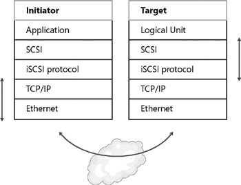
Figure 12-2: iSCSI protocols stack layers
Once the disks are configured and connected, they appear and behave just like local disks attached to the system. Microsoft applications supported on Windows with local disks that are also supported with iSCSI disks include Exchange, SQL Server, Microsoft Cluster Services (MSCS), and SharePoint Server. Most third-party applications for Windows are also supported when used with iSCSI disks.
Performance-related feature enhancements new to Windows Server 2008 in the iSCSI Software Initiator include implementation of Winsock Kernel interfaces within the iSCSI driver stack, as well as Intel Slicing by 8 Algorithm for iSCSI digest calculation.
Additional features that are also supported in previous Windows versions include the following:
-
Support for IPV6 addressing
-
IPSec support
-
Microsoft MPIO support
-
Multiple connections per session (MCS)
-
Error Recovery Level 2
Advantages of iSCSI SAN connected storage include:
-
Leverages existing Ethernet infrastructures
-
Provides the interoperability and maturity of IP
-
Has dynamic capacity expansion
-
Provides for simpler SAN configuration and management
-
Provides centralized management through consolidation of storage
-
Offers scalable performance
-
Results in greater storage utilization
iSCSI components offer higher interoperability than FC devices, including use in environments with heterogeneous storage. iSCSI and FC SANs can be connected using iSCSI bridge and switch devices. When using these components, it’s important to test whether the Fibre Channel storage on the other side of the iSCSI bridge meets interoperability requirements. Because a Windows host connects to iSCSI bridges through iSCSI, adherence to iSCSI and SCSI protocol standards is assumed and FC arrays that do not pass the Logo tests (especially SCSI compliance) can cause connectivity problems. Ensure that each combination of an iSCSI bridge and Fibre Channel array has passed Logo testing and is specifically supported by the storage vendor.
Some considerations and best practices for using iSCSI storage area networks are detailed in the following sections.
Performance Considerations
Ensure that your storage array is optimized for the best performance for your workload. Customers should choose iSCSI arrays that include RAID functionality and cache. For Exchange configurations and other I/O throughput applications that are sensitive to latency, it’s especially important to keep the Exchange disks in a separate pool on the array
One common misconception about iSCSI is that throughput or IOPS on the host is the limiting factor. The most common performance bottleneck for storage area networks is actually the disk subsystem. For best results, use storage subsystems with large numbers of disks (spindles) and high RPM drives to address high-performance application requirements. Maximize the number of spindles available on the iSCSI target to service incoming requests. On the host, the Microsoft iSCSI software initiator typically offers the same IOPS and throughput as iSCSI hardware HBAs, however, CPU utilization will be higher. An iSCSI HBA can be used to reduce CPU utilization or additional processors can be added to the system. Most customers implementing iSCSI solutions don’t experience higher than 30 percent CPU utilization. To prevent bottlenecks on the bus, use PCI-Express based NICs vs. standard PCI. In addition, 10-GB NICs can be used for high transaction-based workloads including streaming backup over iSCSI SANs.
For applications that don’t have low latency or high IOPS requirements, iSCSI storage area networks can be implemented over MAN or WANs links as well, allowing global distribution. iSCSI eliminates the conventional boundaries of storage networking, enabling businesses to access data worldwide and ensuring the most robust disaster protection possible.
Follow the storage array vendor’s best practice guides for configuring the Microsoft iSCSI Initiator timeouts.
Here’s some expert advice: Be sure to use a 512-KB block size when creating iSCSI targets through a storage array or manufacturer’s setup utilities. Use of a block size other than 512 KB can cause compatibility problems with Windows applications.
Security Considerations
The iSCSI protocol was implemented with security in mind. In addition to segregating iSCSI SANs from LAN traffic, you can use the following security methods, which are available using the Microsoft iSCSI Software Initiator:
-
One-way and mutual CHAP
-
IPSec
-
Access control
Access control to a specific LUN is configured on the iSCSI target prior to logon from the Windows host. This is also referred to as LUN masking.
The Microsoft iSCSI Software Initiator supports both one-way and mutual CHAP as well as IPSec.
Networking Best Practices
Following is a list of best practices for using iSCSI storage area devices:
-
Use nonblocking switches, and disable unicast storm control on iSCSI ports. Most switches have unicast storm control disabled by default. If your switch has this setting enabled, you should disable it on the ports connected to iSCSI hosts and targets to avoid packet loss.
-
Segregate SAN and LAN traffic. iSCSI SAN interfaces should be separated from other corporate network traffic (such as LAN traffic). Servers should use dedicated NICs for SAN traffic. Deploying iSCSI disks on a separate network helps to minimize network congestion and latency. Additionally, iSCSI volumes are more secure when you segregate SAN and LAN traffic using port-based VLANs or physically separate networks.
-
Set the negotiated speed, and add more paths for high availability. Use either Microsoft MPIO or MCS (multiple connections per session) with additional NICs in the server to create additional connections to the iSCSI storage array through redundant Ethernet switch fabrics. For failover scenarios, NICs should be connected to different subnets. For load balancing, NICs can be connected to the same subnet or different subnets.
-
Enable flow control on network switches and adapters.
-
Unbind file and print sharing on the NICs that connect only to the iSCSI SAN.
-
Use Gigabit Ethernet connections for high-speed access to storage. Congested or lower-speed networks can cause latency issues that disrupt access to iSCSI storage and applications running on iSCSI devices. In many cases, a properly designed IP-SAN can deliver better performance than internal disk drives. iSCSI is suitable for WAN and lower-speed implementations, including replication where latency and bandwidth are not a concern.
-
Use server-class NICs that are designed for enterprise networking and storage applications.
-
Use CAT6-rated cables for gigabit network infrastructures. For 10-gigabit implementations, Cat-6a or Cat-7 cabling is usually required for use with distances over 180 feet (55 meters).
-
Use jumbo frames, as these can be used to allow more data to be transferred with each Ethernet transaction. This larger frame size reduces the overhead on both your servers and iSCSI targets. It’s important that every network device in the path, including the NIC and Ethernet switches, support jumbo frames.
Common Networking Problems
Common causes of TCP/IP problems include duplicate IP addresses, improper subnet masks, and improper gateways. These can all be resolved through careful network setup. Some common problems and resolutions to them are detailed in the following list:
-
Adapter and switch settings By default, the adapter and switch speed is selected through auto-negotiation and might be slow (10 or 100 Mbps). You can resolve this by setting the negotiated speed.
-
Size of data transfers Adapter and switch performance can also be negatively affected if you are making large data transfers. You can correct this problem by enabling jumbo frames on both devices (assuming both support jumbo frames).
-
Network congestion If the network experiences heavy traffic that results in heavy congestion, you can improve conditions by enabling flow control on both the adapter and the switch.
Performance Issues
IOPS and throughput are typically the same for hardware and software initiators; however, using a software initiator can create higher utilization of the CPU. Most customers do not experience CPU utilization above 30 percent in servers using the Microsoft iSCSI Software Initiator with 1 Gigabit networks. Customers can set up initial configurations using the Microsoft iSCSI Software Initiator and measure CPU utilization. If CPU utilization is consistently high, a TCP/IP offload NIC that implements Receive Side Scaling (RSS) or Chimney Offload can be evaluated to determine the benefit of lowered CPU utilization on the server. Alternatively, additional CPUs can be added to the server. Some enterprise class NICs include RSS as part of the base product, so additional hardware and drivers to use RSS are not needed.
Here’s some expert advice: Windows Server 2008 includes support for GPT disks, which can be used to create single volumes up to 256 terabytes in size. When you are using large drives, the time required to run chkdsk.exe against the drive should be considered. Many customers opt to use smaller LUNs to minimize chkdsk.exe times.
Improving Network and iSCSI Storage Performance
Network performance can be affected by a number of factors, but generally incorrect network configuration or limited bandwidth are primary causes.
Additional items to check include the following:
-
Write-through versus write-back policy
-
Degraded RAID sets or missing spares
Performance Monitor/System Monitor
A Performance Monitor log can give clues as to why the system is hanging. Look for the system being I/O bound to the disk as demonstrated by a high “disk queue length” entry. Keep in mind that the disk queue length for a given SAN volume is the total number divided by number of disk spindles per volume. A sustained reading over 2 for “disk queue length” indicates congestion.
Also, check the following counters:
-
Processor \ DPCs queued/sec
-
Processor \ Interrupts/sec
-
System \ Processor queue length
There are no magic numbers that you look for, but there are deviations that you should look for. The counters just listed help check for hardware issues such as a CPU-bound condition, high interrupt count, and high DPC count, which could indicate stalling at the driver queue.
Deployment
Using Windows as an iSCSI host is also supported with Windows 2000, Windows Server 2003, and Windows XP as a separate download from http://www.microsoft.com/ downloads.
iSCSI Configuration
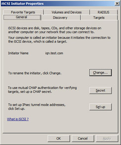
iSCSI initiator configuration can be launched from the control panel (classic view) or from Administrative Tools. iSCSI is supported with all SKUs and versions of Windows Server 2008, including the Windows server core installation option. When using the Windows server core installation option, iSCSICLI must be used to configure connections to iSCSI targets:
More information on iSCSI support in Windows is available at http://www.microsoft.com/WindowsServer2003/technologies/storage/iscsi/default.mspx. More information on the IETF iSCSI Standard is available from the IETF (www.ietf.org).
–Suzanne Morgan
Senior Program Manager, Windows Core OS
–Emily Langworthy
Support Engineer, Microsoft Support Team
iSCSI Remote Boot
Beginning with Windows Server 2003, you could also use iSCSI in “boot-from-SAN” scenarios, which meant that you no longer had to have a directly attached boot disk to load Windows. Being able to boot over an IP network from a remote disk on a SAN lets organizations centralize their boot process and consolidate equipment resources-for example, by deploying racks of blade servers.
Booting from SAN
To boot from SAN over an IP network on Windows Server 2003, you needed to install an iSCSI HBA that supported iSCSI boot on your server. This is because the HBA BIOS contains the code instructions that make it possible for your server to find the boot disk on the SAN storage array. The actual boot process works something like this:
-
The iSCSI Boot Firmware (iBF) obtains network and iSCSI values from a DHCP Server configured with a DHCP reservation for the server, based on the server NIC’s MAC address.
-
The iSCSI boot firmware then reads Master Boot Record (MBR) from the iSCSI target and transfers control. Then the boot process proceeds.
-
Windows start=0 drivers then load.
-
The Microsoft BIOS iSCSI parameter driver then imports configuration settings used for initialization (including the IP address).
-
An iSCSI login establishes the “C:\” drive.
-
The boot proceeds to its conclusion, and Windows then runs normally.
In addition to now having the iSCSI Software Initiator integrated directly into the operating system, Windows Server 2008 also includes new support for installation of the operating system directly to the iSCSI volume on the SAN. This means you can boot from your Windows Server 2008 media, and the iSCSI connected disk now automatically shows up in the list of connected disks that you can install the operating system onto. This provides the same kind of functionality as the iSCSI HBA that was needed in Windows Server 2003 while reducing your cost because you’re able to use commodity NICs. In addition, Windows Server 2008 can be used in conjunction with System Center Configuration Manager 2007 to easily manage your boot volumes on the SAN.
Our experts will now give us more details on booting Windows Server 2008 from a SAN:
Windows Server 2008 adds support to natively boot Windows remotely over a standard Ethernet interface. This enables Windows servers, including blade servers with no local hard drive, to boot from images consolidated in a data center or centralized storage location on an IP network.
Parameters needed to boot Windows are stored in low-level memory by the server option ROM, NIC option ROM, or PXE. They are used by the Windows Boot Manager to bootstrap Windows using standard Interrupt 13 calls and the iSCSI protocol. Customers who want to remotely boot their servers using iSCSI should look for servers or network interface cards that implement the iBFT (ISCSI BIOS Firmware Table) specification, which is required for iSCSI boot using the Microsoft iSCSI Software Initiator. The remote boot disk appears to Windows as a local drive. Boot parameters for the boot disk can be configured statically in the NIC or server option ROM or via a Dynamic Host Control Protocol (DHCP) reservation. Configuration through a DHCP reservation for the server based on a MAC address allows for the most flexibility to dynamically point the server to alternate boot images. Previously, booting a Windows server required an expensive and specialized HBA.
iSCSI provides lower-cost SAN connectivity and leverages the IP networking expertise of IT administrators. Many customers these days are migrating their DAS to storage area networks. Migrating boot volumes to a central location offers similar advantages for data volumes.
Examples of new hardware products that support iSCSI boot natively via the iBFT in firmware or option ROMs include the following:
-
IBM HS20 Blade Server
-
Intel Pro/1000 PF and PT network adapters
-
Additional products to be announced this year
Examples of products that support iSCSI boot natively via PXE ROM implementation and can be used with existing hardware include the following:
-
EmBoot Winboot/i
Installation Methods
For rapid deployment, Windows Server 2008 can be directly installed to a disk located on an iSCSI SAN. A bare-metal system with native iSCSI boot support can be installed using the following methods:
-
Boot from Windows Server 2008 Setup Installation media (DVD)
-
Boot from WinPE, and initiate installation from directory on a network-connected drive
-
Windows Deployment Services (included in the box in Windows Server 2008)
-
System Center Configuration Manager 2007
-
Third-party deployment tools
Scripts and automated installation tools (including unattend.xml) typically used with locally attached drives can also be used with iSCSI-connected disks.
Once Windows Server 2008 is installed, the boot image can be set as a master boot image using Sysprep. Customers should use the LUN-cloning/image-cloning feature available in most iSCSI storage arrays to create additional copies of images quickly. Using LUN cloning allows the image to be available almost immediately and booted even before the copy is complete.
Windows Deployment Services (WDS) assists with the rapid adoption and deployment of Windows operating systems. Windows Deployment Services allows network-based installation of Windows Vista and Windows Server 2008 to deploy Windows Server 2008 to systems with no operating system installed.
Installation to an iSCSI Boot LUN
The following steps are used to install Windows Server 2008 directly to an iSCSI boot LUN:
-
Configure iSCSI target according to the manufacturer’s directions. Only one instance of the boot LUN must be visible to the server during the installation. The installation might fail if multiple instances of the boot LUN are available to the server. It is recommended that the Spanning Tree Protocol be disabled on any ports that are connected to Windows Server 2008 hosts booting via iSCSI. The Spanning Tree Protocol is used to calculate the best path between switches where there are multiple switches and multiple paths through the network.
-
Configure iSCSI pre-boot according to the manufacturer’s directions. This includes configuring the pre-boot parameters either statically or via DHCP. If iSCSI is configured properly, you get an indication during boot time that the iSCSI disk was successfully connected.
-
Boot the system from the Windows Server 2008 Setup DVD, or initiate installation from a network path containing the Windows Server 2008 installation files.
-
Enter your Product Key.
-
Accept the EULA.
-
Select Custom (Advanced).
-
Select the iSCSI Disk. You can distinguish the iSCSI boot disk from other disks connected to the system by checking the size of the disk, which will map to the size of the disk you created in step 1.
-
Windows will complete installation and automatically reboot.
The ability to boot a Windows Server using the Microsoft iSCSI Software Initiator is also available for Windows Server 2003 as a separate download. Windows Server 2008 provides this capability out of the box and provides more direct integration with Windows Server 2008 Setup.
Windows Server 2008 and previous versions of Windows continue to support booting from a remote drive on SAN using a more expensive/specialized HBAs, including iSCSI or Fibre Channel HBAs. The Microsoft iSCSI Architecture integrates the use of iSCSI HBAs (host bus adapters) within Windows. Only HBAs that integrate with the Microsoft iSCSI Initiator service to complete login and logout requests are supported by Microsoft. For a list of supported HBAs, see the Windows Server Catalog of Tested Products at http://www.windowsservercatalog.com.
–Suzanne Morgan
Senior Program Manager, Windows Core OS
–Emily Langworthy
Support Engineer, Microsoft Support Team
iSNS Server
Finally, the Internet Storage Naming Service (iSNS) is another optional feature in Windows Server 2008. This naming service assigns iSCSI initiators to iSCSI targets (storage systems). In Fibre Channel SANs, this functionality is in the FC switch. By providing this functionality as an optional component of Windows Server 2008, you can avoid the expense of a managed switch having name-server functionality. iSNS is usually deployed to help manage larger iSCSI SAN environments that include multiple initiators and multiple targets.
Let’s hear once again from our experts concerning this feature to learn more about it:
The Microsoft Internet Storage Name Service (iSNS) Server included in Windows Server 2008 adds support to the Windows operating system for managing and controlling iSNS clients. More information on the iSNS Standard is available from the IETF (www.ietf.org).
Microsoft iSNS Server is a Microsoft Windows service that processes iSNS registrations, deregistrations, and queries via TCP/IP from iSNS clients. It also maintains a database of these registrations. The Microsoft iSNS Server package consists of Windows service software, a control-panel configuration tool, a command-line interface tool, and WMI interfaces. Additionally, a cluster resource DLL enables a Microsoft Cluster Server to manage a Microsoft iSNS Server as a cluster resource.
A common use for Microsoft iSNS Server is to allow iSNS clients-such as the Microsoft iSCSI Initiator-to register themselves and to query for other registered iSNS clients. Registrations and queries are transacted remotely over TCP/IP. However, some management functions, such as discovery-domain management, are restricted to being transacted via WMI.
Microsoft iSNS Server facilitates automated discovery, management, and configuration of iSCSI and Fibre Channel devices (using iFCP gateways) on a TCP/IP network, and it stores SAN network information in database records that describe currently active nodes and their associated portals and entities. The following are some key details about how iSNS Server operates:
-
Nodes can be initiators, targets, or management nodes. Management nodes can connect to iSNS only via WMI or the isnscli tool.
-
Typically, initiators and targets register with the iSNS Server, and initiators query the iSNS Server for a list of available targets.
-
A dynamic database stores initiator and target information. The database aids in providing iSCSI target discovery functionality for the iSCSI initiators on the network. The database is kept dynamic via the Registration Period and Entity Status Inquiry features of iSNS. Registration Period allows the server to automatically deregister stale entries. Entity Status Inquiry provides the server a pinglike functionality to determine whether registered clients are still present on the network, and it allows the server to automatically deregister clients that are no longer present.
-
The State Change Notification Service allows registered clients to be made aware of changes to the database in the iSNS Server. It allows the clients to maintain a dynamic picture of the iSCSI devices available on the network.
-
The Discovery Domain Service allows an administrator to assign iSCSI nodes and portals into one or more groups, called Discovery Domains. Discovery Domains provide a zoning functionality, where an iSCSI initiator can discover only iSCSI targets that share at least one Discovery Domain in common with it.
–Suzanne Morgan
Senior Program Manager, Windows Core OS
–Emily Langworthy
Support Engineer, Microsoft Support Team
EAN: 2147483647
Pages: 138