See
See Local Area Data Channel (LADC)
See local area network (LAN)
See LAN emulation (LANE)
An Asynchronous Transfer Mode (ATM) technology that enables local area network (LAN) traffic such as Ethernet frames to be carried over an ATM network. LAN emulation (LANE) lets you use ATM as a backbone for connecting LANs.
How It Works
Ethernet and ATM technologies are difficult to connect because ATM is a connection-oriented technology and Ethernet is a broadcast-based connectionless technology. Also, Ethernet frames and ATM cells are different in format and addressing.
For an ATM network to act as a backbone for connecting Ethernet LANs, it must support MAC-to-ATM address mapping. LANE converts variable-length Ethernet frames into fixed-length ATM cells for transmission over the ATM backbone. LANE services run on one or more network servers and map ATM endpoint addresses to non-ATM endpoint Ethernet MAC addresses. These services enable users on ATM networks to transparently access resources on Ethernet networks and vice versa. LANE clients run on bridges, routers, or servers and must reside on each end station of the emulated LAN. Each client has both a MAC address and an ATM address, which is a 20-byte network service access point (NSAP) address. A bridge or router connects the ATM network to the Ethernet network.
When a user on an ATM network wants to access a resource on the Ethernet LAN, the client sends an address resolution message (ARM) to the LANE server, which forwards the message to a bridge or router connected to the Ethernet network. If the bridge or router knows the destination MAC address, it acts as a proxy and forwards the message to the destination client; if it doesn’t know the destination MAC address, it relays the message to the broadcast unknown server (BUS), a LANE service that broadcasts the message to all stations on the Ethernet LAN.
NOTE
LANE can also be used for connecting Token Ring networks using an ATM backbone.
See also Asynchronous Transfer Mode (ATM), MAC address
The integration of LAN-based networks using protocols such as IPX/SPX or TCP/IP with SNA-based host systems such as IBM mainframes and AS/400 systems.
How It Works
Systems Network Architecture (SNA) networks originally developed separately from local area networks (LANs). As a result, both types of network have their own PC adapters, cabling, and protocols. LANs are built primarily around Ethernet using NetBEUI, IPX/SPX, or TCP/IP protocols, and they are connected into wide area networks (WANs) using routers and bridges. LANs and WANs support only non-SNA protocols.
As a result, many large companies have developed a two-tier network, consisting of a traditional LAN-based Ethernet network and an entirely separate SNA host-based network. However, because of the cost of maintaining separate networks, many have merged their SNA-only networks with non-SNA networks.
Early attempts at LAN-host integration involved directly connecting PC computers to IBM host systems using SNA hardware adapters and SNA protocols across a dedicated SNA network. Each PC was connected to a local IBM control unit such as an IBM 3174 or IBM 5294 using coaxial or twinax cabling. Standards were developed to allow SNA and non-SNA protocols to share the same network, but networking engineers soon found that mixing SNA and TCP/IP was like mixing oil and water, especially with regard to WAN connections, in which Data Link Control (DLC) timeouts and other difficulties made network management complex.
One solution is to install a TCP/IP protocol stack directly on the mainframe host, but this often results in degradation of host performance and additional challenges in terms of IP address administration.
Another solution is the LAN-to-SNA gateway. The gateway computer lets desktop PCs access applications and data on the mainframe host using traditional LAN protocols. TCP/IP is used to connect the desktop PC and the SNA gateway, while SNA is used to connect the SNA gateway and the mainframe host. This LAN-to-SNA gateway solution has become the de facto standard for providing host access to LAN-based PCs. An example of an SNA gateway application is Microsoft SNA Server, which provides LAN-to-SNA gateway services over a variety of network protocols that include NetBEUI, TCP/IP, IPX/SPX, Banyan VINES, and AppleTalk.
See Server service
See Workstation service
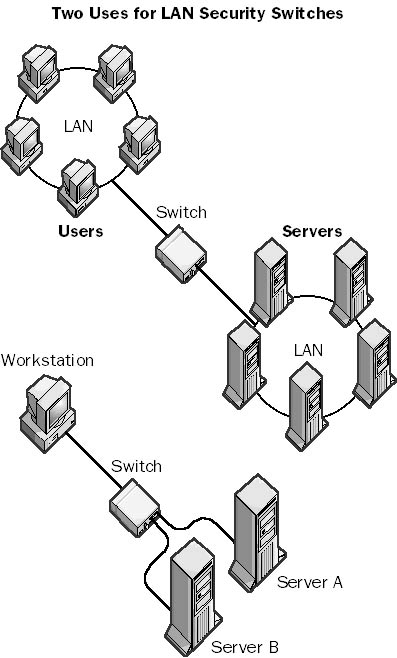
A type of manual switch that can be used to physically disconnect two or more local area network (LAN) segments. LAN security switches create a physical break in a circuit, preventing the flow of data between the connected segments. LAN security switches are available for both copper cabling and fiber-optic cabling. A fiber-optic LAN security switch has a small mirror inside that rotates when you manually flip a switch or rotate a dial to open or close the connection. You cannot operate LAN security switches remotely using electronic means; they must be operated manually.
LAN security switches are typically used in high-security networking environments that must meet the highest government or military security standards. For example, a network supervisor can use a LAN switch at the end of the day to physically disconnect a portion of the network that includes servers that store sensitive data, thus preventing users from accessing the servers during off hours. This is generally more convenient and safer than going into the server room and unplugging connectors from a hub.
Graphic L-1. LAN security switch.
A physical portion of a local area network (LAN) that is separated from other portions by bridges or routers. LANs are often “segmented” using bridges in order to improve network performance. Bridges are smart devices that build MAC-level routing tables that forward network traffic on the basis of the destination MAC address of each frame. If the destination address of a frame is a machine in the local LAN segment, bridges attached to that segment will not allow the frame to pass; this reduces unneeded network traffic in other segments attached to the bridge.
TIP
Segmentation improves performance of Ethernet networks by reducing the number of stations in each segment of the LAN that must compete with each other for access to the network. Bridges are generally used for segmenting smaller LANs because they are cheaper and require no special configuration. You place a bridge between your department or workgroup hub and the main network backbone to improve traffic on your local segment.
Graphic L-2. LAN segment.
The current configuration information for drivers and services when a user successfully logs on to a Microsoft Windows 2000 or Windows NT system. This information is copied to the LastKnownGood control set in the registry and can be used to recover your system if you cannot log on again (for example, if you add or upgrade a driver that is incorrect for your hardware configuration).
How It Works
If you modify your system and are unable to log on again, you can restart your system, press F8 in Windows 2000 or Spacebar in Windows NT, and follow the prompts to reset the Windows configuration.
See Local Address Table (LAT)
A collision on an Ethernet network that is detected late in the transmission of the packet. Late collisions can result from defective Ethernet transceivers, from having too many repeaters between stations, or from exceeding Ethernet specifications for maximum node-to-node distances.
How It Works
Signals on a cable do not travel instantaneously from point to point. Instead, they travel at a fixed speed, which is near the speed of light on copper cabling. If segments of an Ethernet network are too long, collisions can occur that are not detected by the stations on the network. This can result in lost or corrupted data. Collisions are natural on an Ethernet network, and they occur when two stations transmit their signals simultaneously or almost simultaneously. When the stations detect the collision (the concurrent signal from the other transmitting stations), they stop their transmission and wait a random time interval before attempting a retransmission. But the Ethernet standard specifies that if a station on the network is able to transmit 64 bytes or more before another signal is detected, the first station is considered to be “in control” of the wire and can continue to transmit the remainder of its frame, while the second station must stop transmitting and wait.
If the distance between two transmitting stations exceeds the particular Ethernet specification, the stations might not become aware soon enough that another station already has control of the wire. The resulting collision of signals results in a data packet that is more than 64 bytes in length, which is allowable but which contains cyclical redundancy check (CRC) errors, resulting in unreliable communication.
The delay that occurs when a packet or signal is transmitted from one part of a network to another. A network with high latency can experience unpredictable delays. These delays usually do not affect data transmission appreciably since network protocols such as Internet Protocol (IP) are connectionless, but they have a serious impact on transmissions such as streaming audio and video because the human ear and eye can easily detect latency in these forms of transmission. The term “latency” can also refer to the delay in forming a connection, such as the 15 to 30 seconds required to establish a modem connection.
Intrinsic latency in a transmission is caused by the finite transmission speed of the electrical signals through the wires (or the light signals through the fiber-optic cabling). Intrinsic latency cannot be eliminated but is usually quite small. Much greater latency is usually introduced into a network by gateway devices such as routers and bridges, which process packets and perform protocol conversion. The latency for a bridge is thus the time delay between the moment when the packet enters one port of the bridge and the moment when it leaves another port—usually a fraction of a millisecond.
A media-independent tunneling protocol developed by Cisco Systems. The Layer 2 Forwarding (L2F) protocol tunnels data-link layer frames in such protocols as Point-to-Point Protocol (PPP) or Serial Line Internet Protocol (SLIP), making it possible to create virtual private networks (VPNs) over a public network such as the Internet. On the server side, L2F can be used with such features as user authentication through Remote Authentication Dial-In User Service (RADIUS), dynamic allocation of addresses, and quality of service (QoS). L2F is implemented in Cisco routers through Cisco’s Internetwork Operating System (IOS).
How It Works
When using PPP with L2F, for example, PPP provides the connection between a dial-up client and the network access server (NAS) that receives the call. A PPP connection initiated by a client terminates at a NAS located at a PPP service provider, usually an Internet service provider (ISP). L2F allows the termination point of the connection to be extended beyond the NAS to a remote destination node, so the client’s connection appears to be directly to the remote node instead of to the NAS. The function of the NAS in L2F is simply to project or forward PPP frames from the client to the remote node. This remote node is called a home gateway in Cisco networking terminology.
NOTE
L2F has been largely superseded by the newer Layer 2 Tunneling Protocol (L2TP), an Internet Engineering Task Force (IETF) standard protocol that provides a vendor-neutral tunneling solution. L2TP is an extension of the PPP protocol that supports the best features of the Point-to-Point Tunneling Protocol (PPTP) and the L2F protocol.
See also Layer 2 Tunneling Protocol (L2TP)
A form of Ethernet switch that switches packets by looking at their physical addresses (MAC addresses). These switches operate at the data-link layer (or layer 2) of the Open Systems Interconnection (OSI) reference model. They essentially perform a bridging function between LAN segments because they forward frames based on their destination address without any concern for the network protocol being used. Thus, Layer 2 switches are essentially multiport bridges that operate near wire speed and have extremely low latency.
How It Works
Layer 2 switches can be installed transparently into networks. They do not interfere with communication between hosts and routers. Once installed, a Layer 2 switch learns about its connected hosts and networks by examining the source addresses of frames it receives. It builds a cache (database) of these MAC addresses and the ports on the switch to which they are mapped.
When a frame arrives at a port of the switch, the switch examines its destination MAC address and then forwards the frame to the port to which the destination host is connected. If the frame’s source address is unfamiliar, the switch sends the frame to all its other ports except the one through which the frame entered.
Layer 2 switches are often used to create virtual LANs (VLANs), in which the logical segmenting of the network differs from its physical segmentation. Using Layer 2 switches is functionally equivalent to flattening a network into a number of smaller switching domains.
TIP
Use Layer 2 switches for segmenting your Ethernet network into smaller collision domains to improve network performance. Layer 2 switches are generally used in combination with routers to create larger networks. Layer 2 switches are used for creating LAN segments, while the routers provide higher-level functions such as providing wide area access or protocol translation. An alternative is to use a Layer 3 switch, which combines the functionality of an Ethernet switch and a router in one package.
See also Ethernet switch
An Internet Engineering Task Force (IETF) standard tunneling protocol that is used to encapsulate Point-to-Point Protocol (PPP) frames for transmission over TCP/IP, X.25, frame relay, or Asynchronous Transfer Mode (ATM) networks. You can use Layer 2 Tunneling Protocol (L2TP) to create virtual private networks (VPNs) over public networks such as the Internet. Because L2TP is an IETF standard, it provides the interoperability between different VPN vendors that protocols such as Microsoft’s Point-to-Point Tunneling Protocol (PPTP) and Cisco’s Layer 2 Forwarding (L2F) protocol do not, although L2TP essentially combines the best features of these two protocols and is an extension of them. The driving forces behind the development of L2TP include Microsoft and Cisco Systems; L2TP is supported on many Cisco Systems platforms and by the Microsoft Windows 2000 operating system.
How It Works
PPP provides the connection over which L2TP tunnels packets. The tunnel can be initiated by either the dial-up client at the customer premises or by the network access server (NAS) located at the L2TP service provider, typically an Internet service provider (ISP). When the client initiates a connection to the NAS, the NAS is referred to as an L2TP access concentrator (LAC). The LAC forwards its L2TP traffic to the remote node, which is referred to as an L2TP network server (LNS); the NAS performs the server-side function of PPP termination and acts as the receiver of incoming connections. However, if the NAS initiates the L2TP tunnel with the customer premises, the client PC acts as the LNS.
L2TP supports several of the authentication options supported by PPP, including Password Authentication Protocol (PAP), Challenge Handshake Authentication Protocol (CHAP), and Microsoft Challenge Handshake Authentication Protocol (MS-CHAP). You can use L2TP to authenticate the endpoints of a tunnel to provide additional security, and you can implement it with Internet Protocol Security (IPSec) to provide a secure, encrypted VPN solution.
Some of the differences between L2TP and L2F include the following:
L2F has no defined client.
L2F functions in compulsory tunnels only, while L2TP can use voluntary tunnels.
L2TP provides additional features such as flow control and AVP hiding.
L2TP differs from PPTP in the following ways:
PPTP tunnels only over an IP internetwork such as the Internet, while L2TP can use a wider variety of tunnel media.
PPTP supports only one tunnel between two endpoints, while L2TP supports multiple tunnels between two points, each with its own quality of service (QoS).
L2TP headers are compressed and are only 4 bytes, while PPTP has 6-byte headers.
L2TP can be implemented wherever PPTP or L2F is used. A VPN constructed using L2TP can be initiated in two ways:
The client can initiate the tunnel in a similar fashion to PPTP tunnels. For example, Windows 2000 clients can initiate L2TP tunnels and connect with routers that support L2TP, such as Cisco routers.
A NAS can initiate the tunnel, enabling telcos and ISPs to provide corporate customers with complete VPN solutions.
NOTE
When Multilink PPP (MPPP) is used, the PPP links from the customer premises must terminate at the same NAS at the service provider. L2TP has the advantage of supporting multilink configurations in which each link terminates at a different NAS at the provider for more flexibility.
An Ethernet switch that switches packets by looking at both their network address (for example, their IP or IPX address) and their physical address (for example, their MAC address). This type of switch operates at both the network layer (layer 3) and the data-link layer (layer 2) of the Open Systems Interconnection (OSI) reference model. A Layer 3 switch combines the speed of an Ethernet switch with some of the capabilities of a router for building advanced, high-speed Ethernet networks.
How It Works
Layer 3 switches perform on two levels: layer 2 and layer 3. Their layer 3 switching functionality can take one of two forms:
Packet-by-Packet Layer 3 (PPL3) switches: These switches look into every packet to determine its logical layer 3 destination address (such as its destination IP address). PPL3 switches essentially function as high-speed routers with the routing functionality built into its hardware instead of software. Like routers, besides forwarding a packet to its destination, these switches perform other functions that a standard router performs, such as using the packet’s checksum to verify its integrity, updating the packet’s Time to Live (TTL) information after each hop, and processing any option information in the packet’s header. PPL3 switches typically communicate with each other using a routing protocol such as Routing Information Protocol (RIP) or Open Shortest Path First (OSPF) Protocol so that they become aware of the overall topology of the network.
Cut-through switches: These switches look into only the first packet of a series of packets to determine its logical layer 3 destination address (such as the destination IP address), and then switch the remainder of packets in the series using the layer 2 address (MAC address). This leads to higher data throughput rates.
In addition to performing layer 3 switching functions (routing functions), Layer 3 switches perform the functions of Layer 2 switches (bridging functions) at each switch interface. You can group switching interfaces in various ways to allocate bandwidth and contain broadcasts, which makes Layer 3 switches a powerful, scalable technology for building high-speed Ethernet backbone networks.
TIP
You can deploy a Layer 3 switch in your network anywhere a traditional router is used. The following table shows some of the differences between a traditional router and a Layer 3 switch.
Traditional Router vs. Layer 3 Switch
| Feature | Router | Layer 3 Switch |
| Local area network (LAN) protocols supported | IP, IPX, AppleTalk | IP, IPX, AppleTalk |
| Packet-forwarding method | Software-based | Hardware-based |
| Throughput | Lower | Higher |
| Definition of subnet | Per port | Per layer 2 switching domain |
| Support for policy-based routing | Less | More |
| Relationship with bridges | Peer | Layered |
| Cost | Higher | Lower |
See also Ethernet switch
Essentially, a Layer 3 switch that is capable of examining layer 4 of each packet that it switches. In TCP/IP networking, this is equivalent to examining the Transmission Control Protocol (TCP) layer information in the packet. Vendors tout Layer 4 switches as being able to use TCP information for prioritizing traffic by application. For example, to prioritize Hypertext Transfer Protocol (HTTP) traffic, a Layer 4 switch would give priority to packets whose layer 4 (TCP) information includes TCP port number 80, the standard port number for HTTP communication.
Some vendors foresee higher-layer switches that examine layer 5, 6, or 7 information to provide more control over prioritizing application traffic, but this might be just vendor hype.
See Link Control Protocol (LCP)
See Lightweight Directory Access Protocol (LDAP)
An element in the directory hierarchy that is the endpoint of a branch and cannot contain other objects in the way that containers can. An example of a leaf object is a mailbox in the directory of Microsoft Exchange Server, which is found within the Recipients container. You can view and manage objects in the Exchange directory hierarchy using the Exchange Administrator tool.
The term “leaf object” can also describe an endpoint of a branch in Active Directory of Microsoft Windows 2000. Leaf objects (or terminal objects) are found in containers such as organizational units (OUs) and cannot contain other directory objects. You can view and manage objects in Active Directory using Microsoft Management Console (MMC) by installing snap-ins such as Active Directory Users and Computers and Active Directory Sites and Services.
See also Exchange Administrator, Microsoft Exchange Server
Also called a dedicated line, a telecommunications service provided to businesses by telcos and long distance carriers that provides a permanent direct connection between two geographically separate local area networks (LANs). Leased lines are dedicated circuits that the telco reserves for the exclusive use of the customer. They are permanently available, always active, and secure, and they have a consistent quality of service (QoS) and a flat monthly fee. However, they are very expensive compared to dial-up lines, and businesses rarely use their full bandwidth capabilities except in short bursts.
Leased lines are a form of point-to-point connection. Your LAN is connected by bridges, routers, modems, and terminal adapters to the telco’s central office (CO), which sets up dedicated switches to connect you to the destination LAN. The presence of dedicated switches is what makes leased lines so expensive. You would use a leased line to connect a Microsoft Exchange server to the Internet, for example. Since the leased line is always on, there is no connection delay when users try to access the server for their e-mail.
Leased lines are available in 56 Kbps, T1, T3, and higher speeds. They are used mainly for connecting customer premises to the telco CO. The charge for a leased line is based on both bandwidth and distance; leased lines are usually leased for a base monthly cost, and sometimes incur an extra monthly charge proportional to the traffic carried on the line.
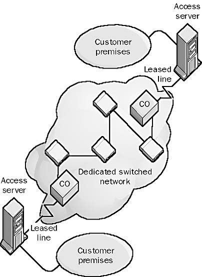
Graphic L-3. Leased line.
NOTE
The opposite of a leased or dedicated line is a dial-up line or switched line.
See also circuit-switched services, packet-switching services
See local exchange carrier (LEC)
See long filename (LFN)
A legal authorization to use software in a given networking scenario. Merely purchasing Microsoft Windows NT, Windows 2000, or any other Microsoft BackOffice software does not legally authorize you to use this software in a given networking scenario; you must also have the appropriate license. You generally obtain a server license for each server and a client access license (CAL) for each client that accesses the server.
In the BackOffice licensing model, each server and client computer is licensed separately. Each BackOffice server requires a server license. The server license is included when you purchase the particular BackOffice product, and it grants you the right to run that product on a particular computer. Each client connection to a BackOffice server requires a CAL, a legal document that grants a client machine the right to access the services provided by a BackOffice server. CALs are generally not included when you buy your BackOffice software and must be purchased separately. Every client machine, no matter what its operating system (Windows, Macintosh, UNIX, and so on), must have a CAL to access either basic Windows NT or Windows 2000 networking services such as file and print services, services for Macintosh, services for NetWare, or Remote Access Service (RAS) or to access any BackOffice application, such as Microsoft Exchange Server.
See also client access license (CAL), License Manager, Per Seat licensing, Per Server licensing
The Microsoft Windows NT service that creates and maintains the database of licensing information for License Manager and generates noncompliance events in the application log.
TIP
If your licensing database information becomes corrupt, you can delete and re-create it by doing the following:
Stop the License Logging Service using the Services applet in Control Panel.
Delete the licensing database files cpl.cfg, llsuser.lls, and llsmap.lls in the %SystemRoot%\system32 directory.
Restart the License Logging Service.
Add your licenses again using License Manager.
See also client access license (CAL), license
A Microsoft Windows NT administrative tool used to manage licenses for Microsoft BackOffice products on a network. You can use License Manager to do the following:
Add or delete client access licenses (CALs) for BackOffice products
Create license groups
Display licensing information
Change licensing from Per Server to Per Seat (one-time conversion)
License Manager can manage licensing on a local machine or over a network.
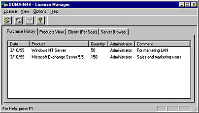
Graphic L-4. License Manager.
NOTE
To configure replication of a server’s licensing information to an enterprise server, use the Licensing tool in Control Panel.
See also client access license (CAL), license
One of two types of client access license (CAL) for Microsoft Windows NT and Microsoft BackOffice. The two licensing modes are Per Server licensing and Per Seat licensing.
TIP
If you are denied a network connection to a server running Windows NT or BackOffice application running on a server because you have exceeded your licensing requirements, you might be able to free up existing connections without having to buy more licenses. Here are a few points to consider:
If you connect to the same server from two different client machines while logged on with the same username, you use up two licenses if you are running in Per Server mode.
IPX connections to basic file and print services on Windows NT take 15 minutes or more to time out when you disconnect.
Internet applications such as Microsoft Internet Explorer, File Transfer Protocol (FTP), and Telnet do not use up licenses.
NetDDE applications such as Clipboard Viewer do not use up licenses.
An Internet protocol for accessing and updating information in an X.500-compliant directory. Users who run Lightweight Directory Access Protocol (LDAP) clients can connect to an X.500 directory service and add, delete, modify, or search for information if they have the appropriate access rights to the directory. For example, a user can use an LDAP client to search a network directory for individuals, users, companies, or other information stored in the directory. LDAP is designed to run over TCP/IP and can access information in both X.500-based directories and many non-X.500-based directories. The current version of LDAP is LDAPv3.
How It Works
LDAP was designed by researchers at the University of Michigan to be an easier, more streamlined version of the standard X.500 Directory Access Protocol (DAP), which requires a full Open Systems Interconnection (OSI) protocol stack to run. LDAP consists of only 16 commands—8 requests and 8 responses. These commands enable users to access, read, modify, and delete information in the directory if they have the appropriate permissions. Objects are referenced using their distinguished names, as in an X.500-based directory.
A directory that is designed specifically for LDAP clients is called an LDAP directory, but this is essentially the same as the X.500 directory structure. An LDAP directory is a distributed directory; portions of the directory can be stored on different directory servers in the network. These directory servers periodically synchronize with each other to keep their information up to date. The root of an LDAP directory branches into countries, then organizations, then organizational units (departments, sections, and so on), and finally into leaf objects, which can include people, servers, printers, and other network objects.
Microsoft Exchange Server stores its directory information in an X.500-style directory. Microsoft Outlook Express is a simple LDAP client that can be used to access personal information about recipients in an Exchange organization.
NOTE
Directory services that are not fully X.500-compliant but can be accessed and managed using LDAP are sometimes called LDAP directory services. An example of an LDAP directory is Active Directory in Microsoft Windows 2000.
Objects within an LDAP directory are identified by their distinguished names, the standard namespace for X.500 directories. Distinguished names are also sometimes referred to as the LDAP Standard Naming Convention.
An LDAP Uniform Resource Locator (URL) is another naming convention that can be used to allow LDAP clients to access objects in an LDAP directory. An LDAP URL is formed by appending the distinguished name of the directory object to the fully qualified domain name (FQDN) of the server containing the LDAP directory. For example, if Active Directory is installed on the server Server7.Microsoft.com, and the distinguished name of the object being referenced in Active Directory is
DC=com,DC=Microsoft,OU=Users,CN=Jeff Smith
the LDAP URL for referencing this object using an LDAP client is
LDAP://Server7.Microsoft.com/CN=Jeff Smith/OU=Users/DC=Microsoft/DC=com
See also Active Directory, distinguished name, X.500
A device that can regenerate or boost the signal strength in serial and parallel transmission so that you can use longer cables. Line boosters typically work with the RS-232 interface and can be used to increase the allowable distance between computers and peripherals (such as printers), usually doubling the distance from 15 meters to 30 meters for serial transmission and from 6 meters to 12 meters for parallel transmission. Line boosters are needed in some networking environments because the signal strength in a serial transmission line decreases with the length of the cable being used.
TIP
Line boosters must be installed at the midway point between the computer and the peripheral, not at one end of the connection.
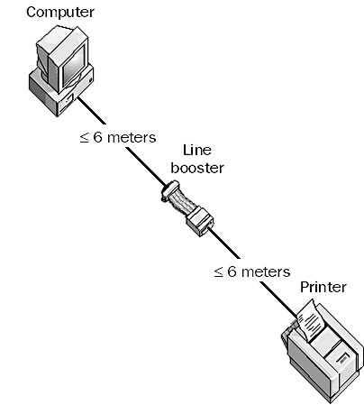
Graphic L-5. Line booster.
A method of placing digital signals on a wire. Line coding specifies the relationship between the binary information in a data bitstream and the square-wave voltage variations on the wire that represent this information electrically.
For example, Integrated Services Digital Network (ISDN) technologies use several different line coding schemes. The U interface, which is located at the ISDN line termination point at the customer premises where a two-wire metallic cable terminates with an RJ-11 jack, uses the 2 binary, 1 quaternary (2B1Q) line coding scheme for Basic Rate Interface ISDN (BRI-ISDN) and the Bipolar with 8 Zero Substitution (B8ZS) scheme for Primary Rate Interface ISDN (PRI-ISDN) in the United States. European ISDN uses 4 binary, 3 ternary (4B3T) for BRI-ISDN and High Density Bipolar 3 (HDB3) for PRI-ISDN.
In the 2B1Q line coding scheme, a block of two binary bits can represent four different values: 00, 01, 10, and 11. These four values are mapped to one quaternary value, which is encoded using four different voltages. The first bit represents a positive or negative voltage, and the second bit represents either 1-volt or 3-volt line potential. The following table shows the four possible combinations.
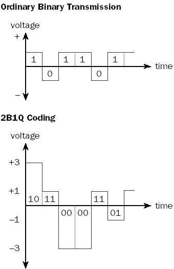
Graphic L-6. Line coding.
Binary Data and Corresponding Voltage Level for 2B1Q Line Coding
| Binary Data Represented | Voltage of Electrical Pulse |
| 00 | -3 |
| 01 | -1 |
| 10 | +3 |
| 11 | +1 |
The result of using 2B1Q line coding for BRI-ISDN is that a single electrical pulse represents 2 binary bits instead of 1 binary bit. This effectively doubles the possible bandwidth of the communication channel, as shown in the illustration.
NOTE
The term “line coding” sometimes refers to signal modulation technologies used in Digital Subscriber Line (DSL) technologies.
Any device that is used to prevent undesirable electrical signals from damaging computer, networking, or telecommunication equipment and to guard against data loss due to electrical noise, sags, and surges. Sometimes called a line shaper, a line conditioner can also ensure that the parameters of the signal remain within specifications for the medium or interface being used, even over excessively long or noisy transmission lines. By maintaining signal integrity, line conditioners can allow communication devices to function at higher throughput rates.
How It Works
Line conditioners contain circuitry that enables them to filter out noise caused by electromagnetic interference (EMI) and other sources. They also contain isolation transformers that electrically isolate the circuitry from unwanted DC voltages, impedance-matching circuitry for reducing unwanted signal reflections, and surge suppressors to guard against high-voltage surges (6000 volts or more) caused by lightning strikes and power failures. Line conditioners can also correct sags (drops) in voltages caused by momentary brownouts, but they are not meant to replace or supply power during a power loss. They often include fault indicators and audible alarms.
You can use line conditioners in the following places:
In power supplies and in uninterruptible power supply (UPS) systems (power conditioners) to protect computers and networking devices from AC surges coming through power lines.
In local area networks (LANs) to protect hubs, routers, and other networking equipment from EMI and unwanted noise coming through the networking cables, and to maintain the integrity of network data signals.
In offices to protect modems, telephones, fax machines, and other equipment by filtering out electrical surges in phone lines and to reduce noise so that the devices can operate at their nominal throughput speeds.
In WAN links for protecting CSU/DSUs (Channel Service Unit/Data Service Units) and access servers connected to Integrated Services Digital Network (ISDN), T1, and other copper telecommunication lines against EMI surges. T1 lines must have line conditioners at regular intervals to ensure the integrity of the signal transmitted over the line.
TIP
Line conditioners can often improve analog modem transmission speeds, enabling high-speed modems to function at their maximum transmission speeds over noisy telephone lines in the local loop.
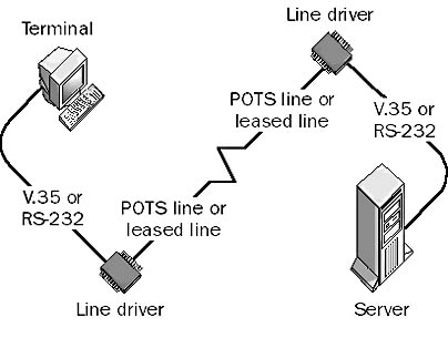
A device that can use installed twisted-pair phone lines or leased lines to connect terminals to servers in different parts of a building or in different buildings. A line driver is essentially a combination of a signal converter and an amplifier for digital signals. The signal converter performs line conditioning, and the amplifier increases the signal strength. Also called a “short-haul” device, a line driver allows a signal produced by a serial transmission device using an interface such as RS-232 to be carried over a longer distance than the interface standard allows, which for RS-232 is only 15 meters.
How It Works
Line drivers are always used in pairs. One line driver is placed at the local site and is connected to the terminal, while the other is located at the remote site and is connected to the server. Line drivers are typically used to extend the maximum distance of serial communication protocols such as RS-232, V.35, X.21, and G.703 and can provide either synchronous or asynchronous communication in various vendor implementations. Considerations for line driver type include full-duplex or half-duplex communication, 2-wire or 4-wire cabling options, and various kinds of connectors. The most common type of line driver uses an RS-232 serial interface for synchronous transmission of data over installed 4-wire telephone cabling. These line drivers can extend the maximum distance of RS-232 serial transmission from 15 meters to several kilometers.
For intrabuilding connections using line drivers, copper unshielded twisted-pair cabling or the installed telephone lines are typically used. For interbuilding connections, fiber-optic cabling is preferred.
NOTE
Line drivers are available for almost every kind of communication mode, from 19.2-Kbps RS-232 serial line drivers over 6 kilometers to 2-Mbps single-mode fiber-optic line drivers over 18 kilometers. Line drivers for parallel connections can extend parallel transmission of data from about 6 meters to several kilometers. Line drivers are also used in implementation of T1 lines.
Graphic L-7. Line driver.
TIP
When you use line drivers, your maximum bandwidth and transmission distance are inversely related—that is, the longer the line, the less bandwidth you have.
For connecting data terminal equipment (DTE) such as two computers, you should use a modem eliminator instead.
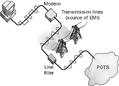
A device used to suppress noise in a transmission line or cable, caused by electromagnetic interference (EMI). EMI is produced by nearby power lines, motors, generators, and other sources. EMI can introduce noise into a transmission line or cable that can degrade the quality of a signal or even make communication impossible. By inserting a line filter at the appropriate point, you can suppress the noise and potentially improve transmission speeds.
Line filters might be needed in homes or small businesses that use modems to connect to the Internet through a dial-up connection over the local loop. High-speed V.90 modems sometimes have difficulty attaining their top data transfer speeds because of ambient line noise caused by nearby sources of EMI. By placing a line filter at the customer premises between the modem and the Plain Old Telephone Service (POTS) connection, you can filter out noise, which could improve modem speeds.
Graphic L-8. Line filter.
TIP
Before installing a line filter, you should use a radio frequency (RF) spectral analyzer to determine the general frequency of the source of EMI so that you can choose an appropriate line filter. Line filters typically filter out one of the following frequency ranges: low frequency (LF), high frequency (HF), very high frequency (VHF), or ultra high frequency (UHF) signals.
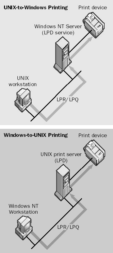
A general TCP/IP daemon on UNIX networks that is used for receiving and spooling print jobs on a print server. The Line Printer Daemon (LPD) print server might be connected directly to the print device, or it might be a network print device that supports LPD. UNIX clients send their jobs to the printer by using the Line Printer Remote (LPR) utility; you can use another utility called Line Printer Queue (LPQ) to check the status of print jobs spooled on the server.
Microsoft Windows NT Server has an optional LPD service that you can install on the machine by installing the Microsoft TCP/IP Printing service, which enables computers running UNIX to send print jobs to the computer running Windows NT by using LPR. Computers running Windows NT can also use the LPR command to send print jobs to a Windows NT server running LPD. The Microsoft TCP/IP Printing service thus provides Microsoft Windows/UNIX printing interoperability for heterogeneous network environments.
Windows 2000 Server uses Microsoft Print Services for UNIX, which provides both LPD and LPR services through two Windows 2000 services:
LPDSVC: Runs on the Windows 2000 print server and receives print jobs from native LPR utilities running on UNIX workstations.
LPRMON: Runs on the Windows 2000 print server and forwards print jobs to native LPD processes running on UNIX computers with attached printers.
TIP
The startup configuration for the LPD service on Windows 2000 is set to Manual by default and should be changed to Automatic if this feature is used.
Graphic L-9. Line Printer Daemon (LPD).
A general TCP/IP utility on UNIX networks that is used for querying the status of the print queue on a print server. The UNIX print server runs a daemon called the Line Printer Daemon (LPD), and the client printing the job uses a utility called the Line Printer Remote (LPR). You can use the lpq command on a server running Microsoft Windows NT that has the Microsoft TCP/IP Printing service installed (or a server running Windows 2000 that has Microsoft Print Services for UNIX installed) to display the status of the print queue on a UNIX LPD server, a Windows NT–based server running the LPD service, or a Windows 2000–based server running the LPDSVC service.
The lpq command displays a list of files on the server that are waiting to be printed. You can also use this command to check the print queue on a UNIX print server; this is one way that Windows NT and Windows 2000 provide interoperability between the UNIX and Windows environments.
Example
Enter the command lpq -S Server7 -P Laser12 to display the status of the print queue Laser12 on a Windows NT–based server named Server7 that is running the LPD service.
A general TCP/IP utility on UNIX networks that is used to send print jobs from clients to print servers. A print server is a UNIX machine running the Line Printer Daemon (LPD) process. In Microsoft Windows NT–based or Windows 2000–based networks that use TCP/IP, you use the lpr command to send print jobs to a UNIX LPD server, a Windows NT–based server running the LPD service, or a Windows 2000–based server running the LPDSVC service.
For example, to configure a computer running Windows NT for Line Printer Remote (LPR) printing to a UNIX LPD print server, use the Network utility in Control Panel to install the optional service called Microsoft TCP/IP Printing on your machine. Then use the Add New Printer Wizard to create a new printer, adding a new LPR port that maps to the IP address or fully qualified domain name (FQDN) of the UNIX host running the LPD service and attached to the print device or the stand-alone network print device.
Example
Enter the command lpr -S Server7 -P Laser12 readme.txt to print the readme.txt file using the print queue Laser12 on the Windows NT–based server named Server7, which is running the LPD service.
NOTE
The file to be printed using the lpr command must be a text file or a file specially formatted for the printer being used (for example, a PostScript file for a PostScript printer).
A device that allows many devices to share the same line. Examples of line sharers include the following:
Host line sharers: Allow multiple terminals or other data terminal equipment (DTE) to be connected to an asynchronous mainframe host over a single, shared serial transmission line using V.35 adapters and cable. You can use host line sharers primarily to broadcast data to the DTEs. Data transmitted by the DTEs can also be buffered in the line sharer until the line is free and the data can be sent to the host. Host line sharers typically use either RS-232 or V.35 serial interface connections.
PSTN line sharers: Allow multiple Public Switched Telephone Network (PSTN) devices, such as phones, fax machines, and modems, to share one or more phone lines by using RJ11 connectors and adapters. You can often program PSTN line sharers to switch between devices based on calling tones, so that you can remotely control data collection equipment over modems in industrial environments. A small line sharer might let you connect four phones or other devices to two shared phone lines for a small office/home office (SOHO). Other line sharers connect large numbers of phones to a relatively small number of phone lines on a first-come, first-served basis in modem-pooling environments.
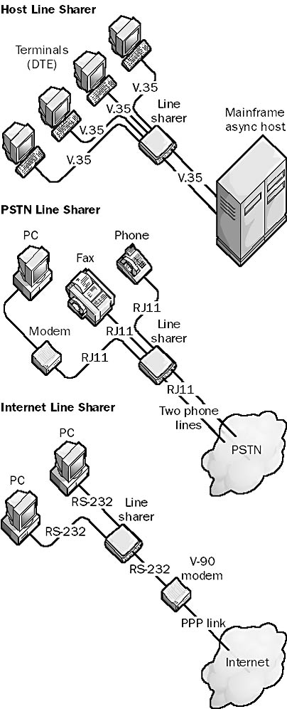
Graphic L-10. Three varieties of line sharer.
Internet line sharers: Typically stand-alone devices that together with RS-232 modem adapters allow several PCs to share one modem for dial-up connection to the Internet. Internet line sharers typically use one IP address to allow multiple users to browse the Internet simultaneously.
A subprotocol within the Point-to-Point Protocol (PPP) protocol suite that is responsible for link management.
How It Works
Link Control Protocol (LCP) operates at the data-link layer (layer 2) of the Open Systems Interconnection (OSI) reference model for networking and is considered a data-link layer protocol. During establishment of a PPP communication session, LCP establishes the link, configures PPP options, and tests the quality of the line connection between the PPP client and PPP server. LCP automatically handles encapsulation format options and varies packet sizes over PPP communication links.
LCP also negotiates the type of authentication protocol used to establish the PPP session. Different authentication protocols are supported for satisfying the security needs of different environments. LCP can negotiate the following authentication protocols:
Password Authentication Protocol (PAP): Transmits passwords in clear text using a two-way handshake
Shiva PAP (SPAP): A vendor-specific implementation of PAP
Challenge Handshake Authentication Protocol (CHAP): Passes a password hash using a three-way handshake and is more secure than PAP or SPAP
Microsoft Challenge Handshake Authentication Protocol (MS-CHAP): Microsoft’s implementation of CHAP, which is more secure than regular CHAP
See also Point-to-Point Protocol (PPP)
A component of Microsoft Exchange Server that verifies the state of a connection between Exchange servers and foreign mail systems. Link Monitors determine whether the messaging link to another mail system is functioning correctly. You should configure Link Monitors for all your connections to remote mail systems from your Exchange organization.
How It Works
The system attendant service sends test messages between the Exchange servers and the foreign mail system at every polling interval and measures the round-trip messaging time.
Link Monitor messages are simply ordinary e-mail messages that the system attendant sends automatically at regular intervals. When a messaging link fails, the Link Monitor can perform a series of escalating actions that can include sending an alert, sending an e-mail notification, or activating a pager.
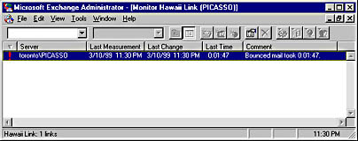
Graphic L-11. Monitoring a link.
A routing method used by dynamic routers in which every router maintains a database of its individual autonomous system (AS) topology. The Open Shortest Path First (OSPF) routing protocol uses the link state routing algorithm to allow OSPF routers to exchange routing information with each other.
How It Works
An AS or routing domain is a group of networks that use the same routing protocol and are under common administration. All routers in an AS have identical link state databases, which contain information about each router’s local state. Routers distribute their local state by using link state advertisements (LSAs), which contain information about neighbors and route costs. From these LSAs, each router builds a hierarchical tree containing least-cost paths to other networks, with the router itself as the root of the tree. Least-cost paths are determined by preassigned factors such as the number of hops between routers, the speeds of the network links connecting them, and traffic flow patterns.
The link state routing algorithm used by the OSPF protocol offers the following advantages over the distance vector routing algorithm used by the Routing Information Protocol (RIP):
RIP routers exchange their entire routing table on a periodic basis, adding to overall network traffic, while OSPF routers exchange only routing table updates.
RIP routers use only the single metric hop count to create their routing tables, while OSPF routers can also use link speeds and traffic patterns to establish cost values for routing traffic.
On the other hand, OSPF requires considerably more processing on the part of the router, making it more expensive to implement. OSPF is also more complex to configure than RIP.
See also distance vector routing algorithm
An operating system derived from the UNIX family of operating systems that is POSIX-compliant and freely distributed through many sites on the Internet. Linux was developed in 1991 by a student from Finland named Linus Torvalds, who still controls the development of the Linux operating system kernel. However, numerous individuals have made important contributions over the years to the operating system. A typical Linux distribution includes the Linux kernel and supporting files, the GNU C/C++ compiler, the Xfree86 version of the X Windows graphical interface, the Apache web server, and other tools and utilities, plus source code for everything. Linux is supported by a network of thousands of users and developers who continue to improve its functionality and performance.
Linux is a good starting point for students interested in learning the UNIX operating system. It has also found a niche in some companies for specific server-based solutions such as Web servers and mail gateways, but some corporations are reluctant to utilize free software such as Linux in their mission-critical operations, because there is no single company responsible for its development and support. Recently, companies such as Red Hat have sought to enhance the usability of Linux in the corporate environment by providing technical support along with easy-to-install Linux distribution.
On the Web
•
Linux Online : http://www.linux.org
•
Red Hat Software home page : http://www.redhat.com
A program that maintains an e-mail mailing list and allows messages to be distributed to its members. For example, a company or organization might set up a list server to run mailing lists for discussing marketing issues, asking and receiving answers from technical support, announcing new products and services, or disseminating tips and tricks for using software.
How It Works
Common list server programs include Listserv and Majordomo. Listserv was originally developed for the BITNET/EARN network. Users must first subscribe to a mailing list using a special e-mail command, although many lists also have Web interfaces for subscribing, unsubscribing, posting messages, and receiving help. Once users subscribe to a list, they receive a copy of every message posted to the list, and every message they post is distributed to all members of the list.
NOTE
Microsoft maintains a number of popular mailing lists relating to various Microsoft products and services. The URL for subscribing to these lists appears at the end of this entry.
TIP
Don’t subscribe to too many mailing lists at once, because the e-mail traffic might fill your mailbox!
On the Web
•
Search The List of Lists : http://catalog.com/vivian/interest-group-search.html
See logical link control (LLC) layer
A text file that provides a local method for name resolution of remote NetBIOS names into their respective IP addresses on a TCP/IP network. Using lmhosts files is an alternative to using WINS servers for name resolution on Microsoft Windows–based networks. Using a WINS server is generally preferable because it reduces administrative overhead.
How It Works
You can find the lmhosts file in the %SystemRoot%\system32\drivers\etc directory in Windows NT and Windows 2000 and in the \Windows directory in Windows 95 and Windows 98.
Each line in the lmhosts file contains the IP address of a NetBIOS computer on the network, followed by the NetBIOS name of the computer. The computer name can be followed by optional prefixes that identify domains and domain controllers and allow entries to be loaded into the NetBIOS name cache at startup. Comments are prefixed with the pound sign (#). Here is an example taken from the sample lmhosts file included with Windows 95:
102.54.94.97 rhino #PRE #DOM:networking #net group's DC 102.54.94.123 popular #PRE #source server 102.54.94.117 localsrv #PRE #needed for the include
NOTE
The lmhosts file contains mappings for hosts on remote networks only. Mappings are not required for hosts on local networks because these can be resolved using broadcasts. If you are using lmhosts files to resolve NetBIOS names on a network, each computer on the network should have an lmhosts file.
TIP
Place the NetBIOS names that need to be resolved most frequently near the top of the lmhosts file, because the file is parsed linearly from the beginning.
See also hosts file, networks file, protocol file, services file
Providing access to resources on a group of servers in such a way that the workload of serving clients is shared among the servers. Numerous vendors supply hardware and software-based load balancing solutions for enterprise networking. Microsoft in particular implements various forms of load balancing in its products, including the following:
Microsoft Cluster Server (or Windows Clustering in Windows 2000): Provides static load balancing for high availability of shared resources. Each node in a cluster shares its own resources or applications, and if failover occurs, the nodes still running can assume the services of the other nodes. This leads to load balancing and high performance.
Microsoft Proxy Server version 2: Provides load balancing of Winsock Proxy (WSP) client connections across several proxy servers by specifying the servers’ IP addresses in the mspclnt.ini file, which is copied from the server to the client when the WSP client is set up. This file enables clients to randomly select which proxy server to use each time they issue a proxy request.
Microsoft DNS Service in Windows NT Server: Supports round-robin DNS service. If you list several IP addresses for the same host name in a DNS zone file, clients connecting to the DNS server to resolve the host name receive the IP addresses in round-robin fashion. This is a simple form of load balancing.
Microsoft SNA Server version 4: Provides load balancing and fault tolerance for connectivity with AS/400 systems.
Various network devices can also implement load balancing. For example, routers use load balancing when routing tables indicate that two or more routes to a destination have the same cost. This use of routers allows you to use different LAN segments more effectively, resulting in greater availability of overall network bandwidth.
The address that a computer on a TCP/IP network uses to access another computer on the same subnet of the network. For example, consider a TCP/IP network with the following subnet scheme:
Network ID = 202.55.0.0
Subnet Mask = 255.255.240.0
Using this scheme, there are 14 possible subnets for the network:
Subnet 1 has hosts 202.55.16.1 through 202.55.31.254.
Subnet 2 has hosts 202.55.32.1 through 202.55.47.254.
Subnet 3 has hosts 202.55.48.1 through 202.55.63.254.

Subnet 14 has hosts 202.55.224.1 through 202.55.239.254.
Now consider the following three hosts on the network:
Host A = 202.55.38.147
Host B = 202.55.44.12
Host C = 202.55.59.6
From the point of view of Host A, which is located on Subnet 2:
Host B is located on the local subnet (Subnet 2), so Host B’s address is local to Host A.
Host C is located on a remote subnet (Subnet 3), so Host C’s address is remote to Host A.
A component of Microsoft Proxy Server created during the setup process that contains information about your company’s private network. The Local Address Table (LAT) is a text file that specifies the ranges of IP addresses that are used in your private (local) network. IP addresses that are external to your private network are excluded from the LAT. The LAT is used by Proxy Server clients to determine whether they should attempt to contact a host directly or make a proxy request through Proxy Server.
How It Works
The LAT consists of a series of IP address pairs that define either a range of IP addresses or a single IP address. Addresses can be added to the LAT either automatically from the Microsoft Windows NT internal routing tables (which occurs when Proxy Server is first set up) or manually, by entering IP address pairs.
The LAT is contained in a file named msplat.txt and is stored with a client setup program on the proxy server in C:\Mspclnt. This directory is automatically shared; clients can connect to this share to run the client setup program, which configures the client computer to function as a client of the Winsock Proxy (WSP) service. The client setup program attempts to configure the client computer’s Web browser as a client of the Web Proxy service. The client setup program also copies the LAT file to the client. Proxy Server is responsible for ensuring that the client always has the most current version of the LAT.
The LAT is used each time a Windows Sockets application on the client tries to establish a connection to an IP address to determine whether the IP address is on the private network or on an external network. Connections to internal networks are made directly, while connections to remote addresses use the WSP service on Proxy Server.
NOTE
During Proxy Server setup, the LAT is automatically generated from the internal Windows NT routing tables, but these generated addresses might not completely define your private network. You should therefore review the generated list of IP addresses and add any needed IP address pairs until all addresses of your internal network are defined. You should also remove any IP address pairs that define external addresses.
A telco service for transmitting data using line drivers. Local Area Data Channel (LADC), also called telco restricted lines, conforms to the Bell 43401 standard published by AT&T. The LADC standard specifies “dc continuity,” which basically means that metallic (copper) conductors (usually the unshielded twisted-pair cabling used for phone lines) must be used. LADC lines must also be unloaded—that is, without terminators, loading coils, or protection circuitry that can add to the inductance of the line and thus distort signals. LADC lines are available to distances of 5 kilometers from the telco’s central office (CO); the longer the distance, the lower the bandwidth supported.
A group of computers located in the same room, on the same floor, or in the same building that are connected to form a single network. Local area networks (LANs) allow users to share storage devices, printers, applications, data, and other network resources. They are limited to a specific geographical area, usually less than 2 kilometers in diameter. They might use a dedicated backbone to connect multiple subnetworks, but they do not use any telecommunication carrier circuits or leased lines except to connect with other LANs to form a wide area network (WAN).
How It Works
Before you can link computers into a LAN, you must install a network-aware operating system on them to enable them to share resources. The choice of operating system depends on whether the network will be a peer-to-peer network or a server-based network. Microsoft Windows 98 is a good choice for peer-to-peer workgroup LANs, while Windows NT and Windows 2000 offer the security and scalability needed to support a server-based network.
Next, you choose a networking architecture. (The vast majority of LANs use Ethernet.) Then you must install a suitable network interface card (NIC) in an available slot on the motherboard of each node (computer) in the network. You must also install a software driver to control the card’s functions. You use cabling to join the NICs in order to enable the computers to communicate with each other. The most common type of cabling used in LANs is unshielded twisted-pair (UTP) cabling. The cabling is installed in some kind of topology or layout, the most popular of which is the cascaded star topology used in the 10BaseT version of Ethernet. You then choose a protocol to enable the nodes on the network to speak a common “language"; the most popular protocol is TCP/IP, especially for Internet connectivity, although for small stand-alone workgroup LANs that use Windows 95 or Windows 98, NetBEUI is still popular.
See also wide area network (WAN)
A telco in the United States that provides local telephone and telecommunication services to businesses and individuals. “Local exchange” refers to a telco’s central office (CO), and “carrier” refers to a company that “carries” telephone and data traffic for customers. In other words, your local exchange carrier (LEC) is simply the company that sends you a telephone bill for local phone calls. An LEC owns the local loop cabling between its CO and its subscribers’ premises, which are confined to a geographical area known as the local access and transport area (LATA). Any calls that take place within a given LATA are considered local calls and are billed accordingly.
The largest LECs came into existence with the breakup of AT&T in the early 1980s, which led to the formation of several independent Regional Bell Operating Companies (RBOCs), but there are also a number of smaller independent LECs in the United States, especially in rural areas that were never part of the Bell system. LECs connect their communication networks using inter-exchange carriers (IXCs), which are long-distance carriers such as Sprint, AT&T, and MCI WorldCom.
The Telecommunications Act of 1996 changed the landscape of the telephone system in the United States by allowing LECs to compete in the deregulated long-distance market and by allowing IXCs to provide services directly to customer premises through mergers, acquisitions, and new technologies. Before 1996, each LEC was also an incumbent local exchange carrier (ILEC) that was the sole provider of telephone services to subscribers in its geographical region. The Telecommunications Act allowed companies to become competitive local exchange carriers (CLECs) that could compete with ILECs in their area by leasing or purchasing services from the ILECs or installing their own systems. LECs have an advantage in that they already own a right-of-access to customer premises, while IXCs have an advantage in that they are larger, more highly capitalized companies that can afford to invest heavily in new technologies and services or even acquire LECs directly.
See also inter-exchange carrier (IXC)
In Microsoft Windows NT–based networks, a type of group that exists only on the local computer on which it is created. On a Windows NT member server or workstation, local groups reside in the local security database on the computer. A local group created on a domain controller, however, exists on all domain controllers in the domain because domain controllers in the same domain share the same security database.
Local groups are used within an enterprise-level Windows NT network to provide users with permissions for accessing network resources and rights for performing system tasks. You generally create local groups for specific groups of resources on the network and assign these local groups suitable permissions on the resources. A collection of global user accounts can be made into a global group. Global groups are placed into local groups to give users access to resources on the network. This process is referred to as AGLP. Note that local groups can contain global user accounts and global groups from any trusted domain, but they cannot contain other local groups.
A Windows 2000–based network can have both local groups and domain local groups. Local groups are for computers running Windows 2000 that are not part of a domain, and they exist only within the local security database of the computer on which they were created. Local groups are used for granting users who are interactively logged on to a computer running Windows 2000 access to resources on that computer. Local groups can contain only local user accounts from the same machine. Domain local groups, however, have a domain-wide scope and provide users with access to resources located anywhere in a domain. You create local groups on a stand-alone machine running Windows 2000 by using the tool Local Users and Groups, which is implemented as a snap-in for Microsoft Management Console (MMC).
TIP
You should use local groups only on stand-alone Windows 2000 servers and workstations that are not part of a domain.
See also AGLP, built-in group, global group, group
See loopback address
The portion of the telephone system that connects your home or office to the nearest central office (CO) of your local telco. The wiring used in the local loop is usually unshielded twisted-pair (UTP) cabling, the transmission method is analog transmission, and the maximum distance from the telco’s CO to the subscriber’s customer premises is about 5 kilometers.
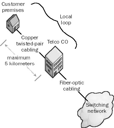
Graphic L-12. Local loop.
NOTE
In many urban and commercial areas, the local loop is being upgraded to Integrated Services Digital Network (ISDN), which uses the same wiring but provides all-digital communication for better voice and data connections. Asymmetric Digital Subscriber Line (ADSL) is another technology that is becoming popular, especially for high-speed residential Internet access.
The network consisting of all computers with the same network number. For example, on a TCP/IP internetwork, a user’s local network consists of all the computers that have the same network ID number, such as 208.16.8.0. Each computer on the local network has a different host ID to identify it among other hosts on the local network. Examples of host IDs for the network 208.16.8.0 could be .25 for 208.16.8.25, .26 for 208.16.8.26, and so on.
The term “local network” can also describe hosts that are on the same TCP/IP subnet in a large internetwork or hosts that are on the same physical LAN segment, such as all the hosts connected to the same hub in an Ethernet network. The term is vague, so you must determine its meaning from the context in which it is used.
A component of the Microsoft Windows NT executive running in kernel mode that is responsible for message passing. In the Windows NT operating system, applications and their supporting environmental subsystems function in a client/server relationship even though both are located on the same machine. The Local Procedure Call Facility (LPC Facility) provides the mechanism for client and server components to send messages to each other. The LPC Facility functions in essentially the same way that remote procedure calls (RPCs) do, except with RPCs the client and server components are located on different machines.
When an application on a computer running Windows NT needs to call an application programming interface (API) function on an environmental subsystem such as the Win32 subsystem, the client uses a placeholder called a stub, which is located in a dynamic-link library (DLL). The stub is used to package and send the parameters being passed to the server subsystem process that implements the call, which unpackages them and executes the called function. The LPC Facility then waits for a response to be issued back. From the application’s point of view, however, the whole process appears to take place locally within the DLL. The application is unaware that the DLL has forwarded the call to another API using the LPC Facility.
The central component of the security subsystem in the Microsoft Windows NT operating system. The Local Security Authority (LSA) is responsible for managing interactive logons to the system. When a user attempts to log on locally to the system by entering a username and password in the logon dialog box, the logon process invokes the LSA, which passes the user’s credentials to the Security Accounts Manager (SAM), which manages the account information stored in the local SAM database. The SAM compares the user’s credentials with the account information in the SAM database to determine whether the user is authorized to access the system. If it finds the user account information in the SAM database, the SAM authenticates the user by creating a logon session and returning the security identifier (SID) of the user and the SIDs of global groups of which the user is a member to the LSA. The LSA then grants the user an access token that contains the user’s individual and group SIDs and their rights; these enable the user to access resources for which he or she has permissions.
The LSA is also responsible for other security-related functions, including the following:
Managing the local security policy on the computer, such as maximum number of logon attempts allowed and account lockout settings
Managing the audit policy on the computer and logging any events generated by the Security Reference Monitor
NOTE
In Windows 2000, Active Directory is functionally located within the LSA in the form of a module called the Directory Service module.
The database of user and group accounts on a server or workstation running Microsoft Windows NT installed as part of a workgroup. In the workgroup security model, each computer running Windows NT is responsible for authenticating users who try to log on locally (interactively) to a particular machine. Each computer in a workgroup maintains its own independent local user and group accounts in its local security database. This is in contrast to a domain security model, in which the security database for all computers in the domain is kept on special machines called domain controllers. The local security database also contains the local security policy for the machine, which governs such things as password expiration and account lockout settings. The local security database is also called the SAM database because it is managed by the Security Accounts Manager (SAM), a component of the Windows NT security subsystem on the local machine.
NOTE
If a machine running Windows 2000 is installed in a workgroup, the database of account information stored on that machine is also called the local security database.
See also Security Account Manager (SAM) database, security subsystem
In Microsoft Windows NT–based networks, a user account that resides in the local security database of a particular Windows NT member server or workstation. When a user has a local account on a computer, the user can log on to the computer interactively.
In a Windows NT–based network based on the workgroup security model, all user accounts are local user accounts and are created using the administrative tool called User Manager, the version of User Manager for Domains that is installed on stand-alone Windows NT member servers and workstations. In a Windows NT–based network that is based on the domain security model, new user accounts created using User Manager for Domains are by default global user accounts that are valid everywhere in the domain and are stored in the Security Accounts Manager (SAM) database on domain controllers. However, in a domain you can also create a local account with User Manager for Domains by clicking the Account button in the New User dialog box and specifying Local Account as the Account Type. This is generally not recommended because local user accounts are not valid throughout the domain and are valid only for logging on interactively to the computer on which they are created.
In a Windows 2000–based network, a local user account is one of three types of user accounts, the others being domain user accounts and built-in accounts. Local user accounts enable users to log on interactively to stand-alone Windows 2000 servers or client computers in a workgroup and access system resources on the machine for which they have suitable permissions. Domain user accounts allow users to log on to a domain and access resources anywhere in the domain. Local user accounts are created using the Local Users and Groups tool, which is implemented as a snap-in for Microsoft Management Console (MMC). Local user accounts are stored in the local security database on the machine on which they are created, while domain user accounts are created in Active Directory and stored in organizational units (OUs).
See also built-in account, domain user account, global user account
A user profile stored locally on a computer running Microsoft Windows NT. A local profile is created for a user the first time the user successfully logs on to his or her computer. If the user does not have a preconfigured roaming user profile at the time of the first logon, Windows NT copies the default user profile to the new local user profile folder.
Local profiles are created for all users who interactively log on to computers running Windows NT so that they can access their own personal settings on that machine. Each user who logs on to a machine thus has his or her own local profile stored on the machine. Local profiles are stored in the folder %SystemRoot%\Profiles.
Each user’s profile is stored in a subfolder that is named after the username of the user and contains the user’s personal settings. The personal settings include both the appearance of the desktop and Start menu and the user’s network connections (such as mapped drives). Even if users have a roaming profile that allows them to log on from any machine in the network and obtain their personal settings, each machine also stores a local copy of their profiles in case the network is down when they try to log on.
Graphic L-13. Local user profile.
NOTE
Windows 2000, Windows 95, and Windows 98 also support local user profiles. In Windows 2000, local user profiles are stored in the Documents and Settings folder.
See also roaming user profile, user profile
A Microsoft Windows 2000 administrative tool available on member servers running Windows 2000 Server and client computers running Windows 2000 Professional that you can use to create and manage local user accounts and local groups on the machine. Local Users and Groups is implemented as a snap-in for Microsoft Management Console (MMC), like other Windows 2000 administrative tools.
You can use Local Users and Groups only if a workgroup security model is being used for your network. In a workgroup, each computer manages its own security and maintains its own local security database of account information. If your network uses a domain security model, all user accounts for the domain are stored in Active Directory, which contains a distributed domain directory database maintained by domain controllers on your network. You cannot install Local Users and Groups on domain controllers; on these machines, you should use Active Directory Users and Computers for creating domain user accounts.
See also Active Directory Users and Computers
A mechanism in Microsoft SQL Server that protects a database against data loss when users simultaneously attempt to modify the same database object. Locking synchronizes users’ access to the database and prevents concurrent data manipulation problems to ensure that data remains consistent and query results are correct.
How It Works
Locking provides concurrency in a multiuser environment—that is, it enables multiple clients to simultaneously access and modify a database without the danger of the data becoming corrupted. If one user locks a portion of the database to view or modify data, that data cannot be accessed or modified by any other user until the first user’s updates have been committed.
SQL Server version 7 uses multigranular locking, in which each database resource is locked at a level appropriate for that kind of resource. The following table shows the various database resources that can be locked in SQL Server 7, in order of decreasing granularity. This range of granularity allows a balance between concurrency (the ability of multiple clients to simultaneously access a database) and performance (speed). For example, highly granular locking such as row-level locking allows more concurrency (different users can simultaneously modify different rows in the same database table), but this increases system overhead because the server must manage more locks.
Database Resources That SQL Server 7 Can Lock
| Locked Resource | Description |
| DB | Locks the entire database |
| Table | Locks an entire database table, including its data and indexes |
| Extent | Locks a contiguous group of eight data pages or eight index pages |
| Page | Locks individual 8-KB data pages or index pages |
| Key | Locks a row within an index |
| RID (row identifier) | Locks individual rows in a table |
SQL Server uses a number of resource lock modes that specify how different database resources can be accessed by concurrent transactions. These include the following:
Shared locks: Allow concurrent transactions to read data—for example, by using transact-SQL SELECT statements. Shared locks allow concurrent reads but lock the resource against modification until the reads are completed. After the data is read, the lock is removed unless a repeatable read is being performed.
Exclusive locks: Lock data so that it can be modified—for example, by using INSERT, DELETE, or UPDATE statements. No other reads or modifications can be performed on the resource while it is exclusively locked.
Other locking modes include update locks, bulk update locks, and intent locks.
A security option for locking a workstation so that only the user who locked it or an administrator can unlock it by pressing Ctrl+Alt+Delete and entering the valid password. If you plan to leave a computer running Microsoft Windows NT or Windows 2000 temporarily and you want to prevent unauthorized access to its console but want to avoid shutting down the system, press Ctrl+Alt+Delete. Then, in the Security dialog box, click the Lock Workstation button on Windows NT, or click the Lock Computer button on Windows 2000.
Network administrators should encourage all users in the enterprise to use Lock Workstation because an unlocked workstation is vulnerable to tampering and can be used to steal or destroy valuable company information. It is easier to lock a workstation than to log off because it takes less time. Locking a workstation also allows the user to continue running applications in the background. Note that you can lock only computers running Windows NT and Windows 2000; this feature is not supported by Windows 95 and Windows 98.
Any file that contains records corresponding to application or operating system events or conditions, usually arranged sequentially by time. Log files are usually delimited text files (such as .csv files) in which each line represents a transaction or logged event, with individual data fields separated by delimiting characters such as commas. Delimited text files can be imported into spreadsheet programs such as Microsoft Excel, database programs such as Microsoft Access, and report and analysis tools such as Crystal Reports for further analysis and graphical display of trends and usage patterns. “Relogging” is the process of taking a log file and sampling it at larger time intervals to reduce the size of the file for archiving purposes while maintaining the overall trend of data within the log.
Numerous processes within the Microsoft Windows operating systems and the Microsoft BackOffice applications maintain logs. Some log functions include the following:
Keeping track of transactions performed on an information store or database (as in Microsoft SQL Server or Microsoft Exchange Server)
Monitoring server or network performance over time when Performance Monitor is used on a Windows NT–based or Windows 2000–based network
Recording details of visitors to Web sites when you use Internet Information Services (IIS)
Recording the details of modem commands or Point-to-Point Protocol (PPP) transmissions when you use Network and Dial-up Connections to connect to an Internet service provider (ISP)
One of the two sublayers into which the data-link layer of the Open Systems Interconnection (OSI) reference model is subdivided for data-link protocols used on local area networks (LANs). The logical link control (LLC) layer is part of the IEEE Project 802 specifications. The LLC protocol is based on the earlier High-level Data Link Control (HDLC) protocol. “LLC” sometimes refers to the IEEE 802.2 protocol itself, which is the most common LAN protocol implemented at the LLC layer.
How It Works
For LAN data-link protocols such as Ethernet, the data-link layer is divided into an upper layer called the logical link control (LLC) layer and a lower layer called the media access control (MAC) layer. The MAC layer coordinates access to the physical layer according to a media access control method, which for Ethernet is the Carrier Sense Multiple Access with Collision Detection (CSMA/CD) scheme. The MAC layer thus provides services to the LLC layer so that protocol data units can be transferred to the medium without any concern about the broadcast, framing, addressing, or error-detection schemes used. The LLC uses the MAC services to provide two types of data-link operations to the network layer above it: LLC1 for connectionless and LLC2 for connection-oriented data-link communication services (known as Type 1 and Type 2, respectively). These LLC services are grouped into two classes:
Class 1 services: Connectionless services used by applications that do not require error detection or flow control.
Class 2 services: Either connectionless (Type 1) or balanced-mode connection-oriented (Type 2) data transfer services. The LLC provides the error detection and recovery, flow control, and resequencing services needed for connection-oriented data transfer.
See also Open Systems Interconnection (OSI) reference model
The process by which users notify a network’s security authority (such as a Microsoft Windows NT domain controller) that they are terminating their session on the network. Users should always log off their computers when they are finished for the day to prevent unauthorized access to the network through their computers by others who might use the building at night.
If you find that users do not log off their computers, try configuring logon hours restrictions on your domain controllers to forcibly disconnect users after work hours. You can also check whether your password policy is too strict, which might encourage users to stay logged on to avoid having to reenter a complex password each time they return to their station.
TIP
In Windows NT and Windows 2000, if you are leaving your desk for only a short time, you can lock your workstation by using Ctrl+Alt+Delete instead of logging off. It’s faster, and it allows applications such as your e-mail program to continue running.
The process by which a user’s credentials are verified by a network security authority so that the user can be granted access to the machine. Logons can be one of two types:
Interactive logons: Occur when users sit at the console of the computer they want to access and enter their credentials in the logon dialog box.
Remote logons: Occur when a user has already logged on interactively to a machine but wants to establish a network connection with a remote computer. For example, if the user tries to map a drive letter to a shared folder on the remote computer, a remote logon must take place during the process so that the remote computer can be sure that the user has the right to perform the action.
When a user attempts an interactive logon to a machine, the user’s credentials are verified by a security authority, which can be one of the following:
The local machine itself, such as a computer running Microsoft Windows NT or Windows 2000 that is configured as part of a workgroup. In the workgroup security model, each machine maintains its own separate list of valid user accounts in its local security database. When a user performs an interactive logon to a stand-alone machine running Windows NT or Windows 2000 that is not part of a domain, the machine itself validates the user’s credentials.
A designated machine or group of machines on the network. For example, in a Windows NT–based network that is based on the domain security model, special machines called domain controllers store and maintain the list of valid user accounts for all users on the network in the domain directory database or Security Account Manager (SAM) database. These domain controllers are used for validating attempts by users logging on to computers in the domain. When the user attempts to log on interactively to the local machine that is part of a domain, the local machine forwards the user’s credentials to a domain controller on the network by using a mechanism called pass-through authentication, and the domain controller authenticates the user’s credentials and informs the user’s local machine that it should allow the user access to the network.
NOTE
In a Windows 2000–based network that uses the domain security model, the directory database is the database component of Active Directory. A successful logon to a machine running Windows NT or Windows 2000 results in an access token being granted to the user, which enables the user to access shared resources on the network for which he or she has suitable permissions.
The hours during which a user has access to the network. In Microsoft Windows NT, administrators use User Manager for Domains to establish logon hours and other restrictions for each user account. In Windows 2000, administrators use Active Directory Users and Computers, which is implemented as a snap-in for Microsoft Management Console (MMC). Logon hours can be applied on either a permit or deny basis.
Graphic L-14. Logon hours.
NOTE
When a user’s logon hours expire, the user can continue to work on the workstation but cannot access any network resources except the resources that are already open, such as the shares that the user is accessing. In Windows NT, you can disconnect users from all network resources when their hours expire by choosing Policies from the User Manager for Domains menu bar, selecting Account, and then selecting Forcibly Disconnect Remote Users From The Server When Logon Hours Expire at the bottom of the Account Policy dialog box.
TIP
For security reasons, you might want to restrict logon hours for ordinary users to company working hours. This reduces the chance of accounts being used for unauthorized access during off hours.
A batch file that automatically runs every time a user logs on to a network. A typical logon script might contain a series of net.exe commands that synchronize the clock of the client computer with a particular server, ensure that mapped network drives are available, restore printer connections, and perform other actions to configure the user’s work environment.
Logon scripts are primarily intended for non–Microsoft Windows and legacy Windows clients that are part of a Windows NT–based or Windows 2000–based network. This is because Windows NT Workstation and Windows 2000 Professional make use of user profiles instead for configuring the user’s desktop, network, and printer connections.
Example
The following simple script runs when a Windows client logs on to a Windows NT Primary Domain Controller. The script synchronizes the workstation’s clock with the server, maps the drive letter K to a share on the server, and then exits.
net time \\pdc /set /yes >nul net use k: \\pdc\home exit
Names of files in Microsoft Windows NT, Windows 95, Windows 98, and Windows 2000, which can be up to 260 characters long and can include letters, numbers, and selected special characters. An 8.3 alias is automatically generated so that MS-DOS and 16-bit Windows-based applications can access the files.
How It Works
The NTFS file system has native support for long filenames, while Windows 95 and Windows 98 use multiple file allocation table (FAT) entries to hold a single long filename, marking these entries with the following unique set of attributes:
Read-only
System
Hidden
Volume label
Windows 95, Windows 98, Windows NT, and Windows 2000 similarly generate MS-DOS 8.3 aliases by using the first six characters (excluding spaces) from the long filename, followed by a tilde and a number, plus a three-character extension using the first three characters after the final period. All characters in the filename and extension are translated to uppercase. The following table shows some long filenames and their MS-DOS aliases.
Long Filenames and Corresponding MS-DOS Aliases
| Long Filename | MS-DOS 8.3 Alias |
| This is my document.doc | THISIS~1.DOC |
| This is my other document.doc | THISIS~2.DOC |
| This was a text document.text | THISWA~1.TEX |
See also 8.3 filename
A testing procedure in telecommunications in which a test signal is sent from a service provider’s central office (CO) to the customer premises and is returned or echoed by the customer premises equipment (CPE) back to the service provider. Loopback tests are used to check line integrity and the proper functioning of customer premises equipment and to diagnose and troubleshoot communication problems. Loopback tests can be performed by wide area network (WAN) access devices such as CSU/DSUs (Channel Service Unit/Data Service Units) and routers to place calls to themselves over a WAN to test the integrity of the WAN link. If the loopback signal fails to return, the WAN link is down and must be repaired. If the loopback signal returns, the device compares the original signal with the returned one; any discrepancies found can be used to troubleshoot communication problems.
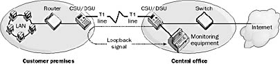
Graphic L-15. Loopback.
For example, if you are a subscriber using an Integrated Services Digital Network (ISDN) line to connect to your service provider, you can usually perform a loopback test yourself. If the Service Profile Identifiers (SPIDs) and ISDN directory numbers have been configured for your ISDN interface, a loopback test will determine
Whether you can connect with your provider’s ISDN exchange. If not, you might have a cable or interface problem.
Whether your ISDN numbers are correctly assigned.
Whether you have caller ID or other advanced ISDN services on your line.
Another type of loopback test is the local loopback test, which a WAN access device uses to test networking connectivity with locally attached network devices. You can also implement a local loopback test by having network application software place a call to the WAN access equipment and having the equipment return an echo to the application.
In TCP/IP networking, the special IP address 127.0.0.1. The loopback address is used to route outgoing IP packets to the TCP/IP protocol stack bound to the network interface card (NIC) and back to the source application without actually placing the packets on the network.
To test whether TCP/IP is installed correctly on a machine running Microsoft Windows, type ping 127.0.0.1 at the command prompt. You can also type the command ping localhost to achieve the same result, or you can even ping any other legal IP address with the form 127.x.y.z. If this test produces an error, your NIC is incorrectly configured or your TCP/IP stack is corrupt. Try removing and reinstalling TCP/IP on your machine. If that fails, try reinstalling the driver for your NIC or replacing the NIC.
See Local Procedure Call Facility (LPC Facility)
See Line Printer Daemon (LPD)
See Line Printer Queue (LPQ)
See Line Printer Remote (LPR)
See Local Security Authority (LSA)