| This example illustrates a link initialization disconnect sequence; that is, the events that would occur when BIOS software uses disconnect (LDTSTOP#) to change the link frequency and width during initialization. Background During initialization, devices that share a HT link must determine the maximum clock frequency and maximum link width supported by both devices. The first step in this process involves a device procedure that establishes a safe but not necessarily optimum clock frequency and link width immediately following reset. Initialization software (BIOS) must tune the link width and frequency. Software simply reads the maximum capability registers within each device, determines the maximum values that each device supports, and loads the link control registers with these values. However, these values do not take effect until BIOS software initiates either a soft reset or LDTSTOP disconnect. This example assumes that the system is designed to perform the disconnect rather than a soft reset. The disconnect method may be chosen because it completes more quickly than a soft reset. Details regarding link initialization can be found in Chapter 12, entitled "Reset & Initialization," on page 275. Setup and Assumptions This example explains the relationships between the various messages, responses, and signals involved in the disconnect sequence. Figure 9-4 on page 226 illustrates an HT-based system with an I/O Controller Hub (ICH) that contains a System Management Controller. The LDTSTOP# signal is an input only to all devices except the ICH in an x86 system. Figure 9-4. Theoretical System with LDTSTOP# Support 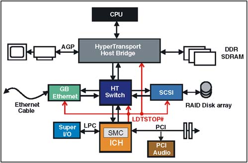 The Host Bridge and ICH must be designed specifically to perform the link initialization disconnect. This requires support of several key features including: -
A trigger mechanism to initiate link initialization disconnect ” The ICH must include a mechanism (e.g. a register) that permits BIOS software to initiate the link initialization disconnect sequence for changing the link frequency and width. -
STPCLK system management message ” The ICH must be able to assert and deassert STPCLK in response to a software request to initiate the link initialization disconnect. The platform must also define an SM Action Field (SMAF) code that identifies the reason for STPCLK being signaled. The host bridge must be designed to detect the message and respond appropriately. -
STOP_GRANT system management message ” The system must support the delivery of the STOP_GRANT message and the associated SMAF code that identifies the reason for sending the message. The ICH must be designed to detect the message and respond appropriately. -
LDTSTOP# signal ” The ICH must be able to assert and deassert LDTSTOP# using the specified sequence and timing required. The Link Initialization Disconnect Sequence The following steps define the sequence of events beginning with BIOS initiation of the sequence to return to normal operation. | Step 1: | The BIOS code initiates the link-initialization disconnect sequence by writing to register within the ICH, in this example implementation. The write transaction is assumed to be a non-posted operation, which requires a TargetDone response. | | Step 2: | The ICH responds by sending a STPCLK assertion SM message to the host with a UnitID that matches the UnitID of the TargetDone response pending for step 1. The STPCLK assertion message contains a SMAF value that defines the reason for STPCLK assertion in this example. | | Step 3: | After the STPCLK assertion message is sent to the host, the ICH is allowed to send the response to the initiating transaction from step 1. Note that this sequence is important to ensure correct ordering of events based on some OS implementations . The response must follow the STPCLK SM message to guarantee that the host does not execute any additional instructions after the initiating command of step 1. | | Step 4: | When the STPCLK assertion message reaches the host, the host reflects the message downstream to all links in the fabric. Reflecting STPCLK assertion downstream has no specific purpose, it is simply earier for the host to reflect all SM messages rather than just some. | | Step 5: | In addition to reflecting the STPCLK assertion message in the downstream direction, the host must also respond to the STPCLK assertion message by broadcasting a STOP_GRANT SM message across all downstream links. This is intended to indicate that the host is ready for the next step in the state transition, and notifies all devices of the power state being entered. | | Step 6: | The ICH asserts LDTSTOP# in response to receiving and decoding the STOP_GRANT system management message and SMAF code. The ICH must delay signaling LDTSTOP# after receiving STOP_GRANT to allow time for STOP_GRANT to reach all other devices in the system. All devices upon detecting LDTSTOP# perform the disconnect sequence that includes updating the link width and frequency based on new values loaded into the Link Control Register. | | Step 7: | LDTSTOP# is deasserted under control of the system management logic. Recall that LDTSTOP# can be deasserted either before or after the link disconnection sequence is complete as described in item 5 on page 224. | | Step 8: | When a device completes the disconnect sequence and has detected LDTSTOP# deasserted, it enters its reconnect sequence. | | Step 9: | After LDTSTOP# is deasserted, the ICH must send the STPCLK deassertion system management message to the host to notify the host that it can resume normal operation (i.e. to exit the STOP_GRANT state). The Host Bridge in turn reflects the STPCLK deassertion message downstream to all chains. | |