HT Signals


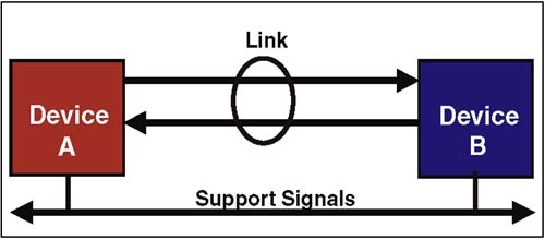
The HT signals can be grouped into two broad categories (See Figure 2-6 on page 27):
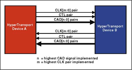
  • The link signal group ” used to transfer packets in both directions (High-Speed Signals).

  • The support signal group ” that provides required resources such as power and reset, as well as other signals to support optional features such power management (Low-Speed Signals).

Figure 2-6. Primary HT Signal Groups

graphics/02fig06.jpg

Link Packet Transfer Signals

The high-speed signals used for packet transfer in both directions across an HT link include:

  • CAD (command, address, data). Multiplexed signals that carry control packets (request, response, information) and data packets. Note that the width of the CAD bus is scalable from 2-bits to 32-bits. (See "Scalable Performance" on page 30.)

  • CLK (clock). Source-synchronous clock for CAD and CTL signals. A separate clock signal is required for each byte lane supported by the link. Thus, the number of CLK signals required is directly proportional to the number of bytes that can be transferred across the link at one time.

  • CTL (control). Indicates whether a control packet or data packet is currently being delivered via the CAD signals.

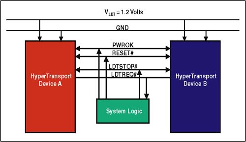
Figure 2-7 illustrates these signals and defines various widths of data bus supported. The variables "n" and "m" define the scaling option implemented. Refer to "Link Initialization" on page 282 for details regarding HT data width and clock speed scaling.

Figure 2-7. Link Signals Used to Transfer Packets

graphics/02fig07.jpg

Link Support Signals

The low-speed link support signals consist of power- and initialization-related signals and power management signals. Power- and initialization- related signals include:

  • V LDT & Ground ” The 1.2 volt supply that powers HT drivers and receivers

  • PWROK ” Indicates to devices residing in the HT fabric that power and clock are stable.

  • RESET# ” Used to reset and initialize the HT interface within devices and perhaps their internal logic (device specific).

  • Power management signals

    • LDTREQ# ” Requests re-enabling links for normal operation.

    • LDTSTOP# ” Enables and disables links during system state transitions.

Figure 2-8. Link Support Signals

graphics/02fig08.jpg


HyperTransport System Architecture
HyperTransportв„ў System Architecture
ISBN: 0321168453
EAN: 2147483647
Year: 2003
Pages: 182

flylib.com © 2008-2017.
If you may any questions please contact us: flylib@qtcs.net