DownStream HT to Expansion Bus Memory Mapping
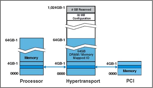
| Downstream memory transactions may be accomplished solely on the basis of mapping registers defined by the bus architecture (e.g. PCI), or may be aided by the Address Remapping Capability block registers when the HT addresses are outside the range of the expansion bus memory address range. Because HT defines a large range of address space for mapping memory and MMIO locations (00_0000_0000h-FC_FFFF_FFFFh), its address space may extend beyond the address range of the secondary bus. Downstream Memory Access Without RemappingThe first example represents the simple case where no remapping of memory addresses is required. This example assumes that the processor memory space is directly mapped to HT address space and to the PCI bus memory address space. This mapping is illustrated in Figure 21-5 on page 486. Note that no remapping is required in this example because the memory addresses assigned to the PCI devices are mapped to the same memory locations of both the processor and HT bus. Figure 21-5. Example of Direct Memory Mapping between CPU, HT, and PCI. In this implementation, the Address Remapping Capability block registers defined by HT for remapping memory can be disabled using the associated control registers. The bridge can simply use the PCI Memory Base and Limit registers for both prefetchable and non-prefetchable memory address space. Memory Accesses with RemappingThe mechanism used for remapping memory addresses includes support for prefetchable and non-prefetchable address space. Two mapping registers are defined for each type of address space:
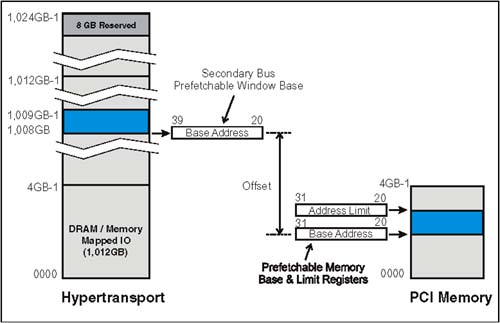
Each register has the same format and function except for the different memory address types that they support. Both registers permit the HT to expansion bus bridge to remap HT memory address space to the expansion bus address space. This capability is needed only in the event that HT space is beyond the range of the expansion bus. The 20-bit value written to these registers by configuration software defines HT address bits 39:20, which is the base address of the HT memory range that is assigned to expansion bus memory. The range of addresses associated with the base address is determined by other registers within the bridge. For example, the PCI Prefetchable Memory Base and Prefetchable Memory Limit registers define the range of prefetchable address space allocated for the PCI bus. Figure 21-6 on page 487 illustrates the registers that would be used when remapping prefetchable memory from HT-to-PCI. In this example, an HT memory address range has been allocated for PCI prefetchable memory. The base address of the address range is specified in the Secondary Bus Prefetchable Window Base register. The 4GB PCI address space allocates a 1GB range of addresses for prefetchable memory. This range is defined by the Prefetchable Base and Prefetchable Limit registers. The bridge uses these registers to recognize an HT address that falls within the prefetchable range and remaps the address to PCI based on the address offset. Remapping of the non-prefetchable address space is based on the same principles, but uses the PCI Memory Base and Memory Limit registers. Figure 21-6. Prefetchable Memory Address Remapping Registers SBNPCtl and SBPreCtlThe Secondary Base Non-Prefetchable Control (SBNPCtl) and Secondary Base Prefetchable Control (SBPreCtl) fields define attributes associated with the memory range specified and permits software to enable and disable the downstream remapping windows . Figure 21-7 on page 488 illustrates the format and definition of each field within the control register. Figure 21-7. SBNPCtl and SBPreCtl Register Format The following list defines and specifies the use of each field:
The following sections provide examples of memory remapping between HT and PCI. Specific examples have been chosen to illustrate the key implementations . |
EAN: 2147483647
Pages: 182