PCI Bus Issues
| Several features of the PCI bus must be handled in the correct fashion when interfacing with the HT bus. For background information and details regarding PCI ordering, refer to MindShare's PCI System Architecture book, 4th edition. PCI Ordering RequirementsTransaction ordering on the PCI bus is based on the Producer/Consumer programming model. This model involves 5 elements:
This model works flawlessly in PCI when all elements reside on the same shared PCI bus. When these elements reside on different PCI buses (i.e. across PCI to PCI bridges, the model can fail without adherence to the PCI ordering rules. The PCI specification, versions 2.2 and 2.3, defines the required transaction ordering rules. These ordering rules are included in this section as review and to identify rules that have may have no purpose in some HT designs. Table 20-1 on page 459 defines the ordering rules or PCI bridges. When reading the table, please note the following:
Table 20-1. PCI Ordering Rules
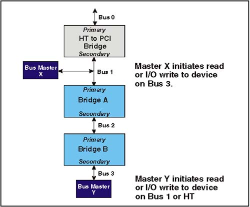
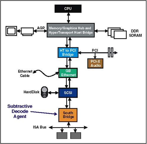
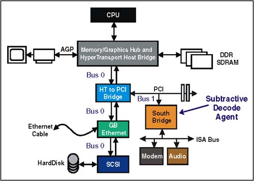
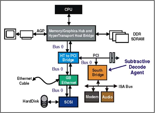
Note that all of the transaction types listed under the heading, "transaction just latched" (except Delayed Write Completions, because the write has already completed) must never be reordered ahead of a previously posted memory write transaction (column 1). These rules are present to enforce proper operation of the producer/consumer model. HT support these rules providing that transactions originated from or targeting PCI devices do not use the PassPW feature in HT. Avoiding DeadlocksPCI ordering rules require that Posted Memory Writes (PMWs) in Row 1, be ordered ahead of the delayed requests and delayed completions listed in columns 2-5. This requirement is based on avoiding potential deadlocks. Each of the deadlocks involve scenarios arising from the use PCI bridges based on earlier versions of the specification. If all PCI bridge designs used in HT platforms are based on 2.1 and later versions of the PCI specification, the PCI ordering rules with "Yes" entries in row 1 can be treated as "Yes/No." Table 20-1 also specifies that Delayed Read Completions and Delayed Write Completions in rows 4 and 5, must be ordered ahead of the Delayed Requests in Columns 2 and 3. These ordering rules arise from potential deadlocks that can occur when two hierarchical bridges are implemented as illustrated in Figure 20-1 on page 460. Refer to MindShare's PCI System Architecture book for a detailed explanation of this deadlock. If a given platform avoids this topology, then the "Yes" entries in rows 4 and 5 can be treated as "Yes/No." Figure 20-1. Topology Causing Deadlock Scenario for Rows 4 and 5 Subtractive DecodePCI employs a technique referred to as subtractive decode to handle devices that are mapped into memory or I/O address space by user selection of switches and jumpers (e.g. ISA devices). Consequently, configuration software has no knowledge of the resources assigned to these devices. Fortunately, these PC legacy devices are mapped into relatively small ranges of address space that can be reserved by platform configuration software. Subtractive Decode: The PCI MethodSubtractive decode is a process of elimination . Since configuration software allocates and assigns address space for PCI, HT, AGP and other devices, any access to address locations not assigned can be presumed to target a legacy device, or may be an errant address. All PCI devices must perform a positive decode to determine if they are being targeted by the current request. This decode must be performed as a fast, medium, or slow decode. The device targeted must indicate that it will respond to the request by signaling device select (DEVSEL#) across the shared bus. When device driver software issues a request with an address that has not been assigned by configuration software, no PCI device is targeted (i.e. no DEVSEL# is asserted within the time allowed) By process of elimination, the subtractive decode agent recognizes that no PCI device has responded and therefore it asserts DEVSEL# and forwards the transaction to the ISA bus, where the request is completed. Subtractive Decode: The Simple HT MethodAn HT system with a single chain can possibly implement subtractive decode without extra host support required of more complex HT systems. Figure 20-2 on page 462 illustrates a simple system with a single-hosted chain. Note that the subtractive decode agent is at the end of the chain. If a request initiated at the host reaches the South Bridge, then the bridge knows that no other HT agents have claimed the transaction based on positive decode; therefore, a subtractive decode is safe. Figure 20-2. Subtractive Decode in a Simple HT System Subtractive Decode: HT Systems Requiring Extra SupportWhen the subtractive decode agent is not at the end of a single-hosted chain, or when more than one HT I/O chain is implemented in a system, subtractive decode becomes more difficult. The ProblemHyperTransport devices in a chain do not share the same bus as in PCI, so a subtractive decode agent cannot detect if a request has not been claimed by other devices on the chain. The SolutionAs described previously, configuration software assigns addresses to all HT, PCI, and AGP devices. Therefore, the host knows when a request will result in a positive decode and when it will not. The specification requires that all hosts connecting to HyperTransport I/O chains implement registers that identify the positive decode ranges for all HyperTransport technology I/O devices and bridges (except as noted in the simple method). One of these I/O chains may also include a subtractive bridge (typically leading to an ISA, or LPC bus). Requests that do not match any of the positive ranges must be issued with the compat bit set, and must be routed to the chain containing the subtractive decode bridge. This chain is referred to as the compatibility chain. The Compat bit indicates to the subtractive decode bridge that it should claim the request, regardless of address. Requests that fall within the positive decode ranges must not have the Compat bit set, and are passed to the I/O chain upon which the target device resides. The target chain may be the compatibility or any other I/O chain. Subtractive Decode: Behind PCI BridgeFigure 20-3 on page 463 illustrates the subtractive decode agent residing on a PCI bus behind a HT-to-PCI Bridge. When the host initiates a request that falls outside the assigned positive address ranges, it will set the compat bit and deliver the request to the HT-to-PCI Bridge. The bridge will detect the Compat bit set and forward the transaction on to the PCI bus where the South Bridge will perform the subtractive decode. Figure 20-3. Subtractive Decode Agent Behind PCI Bridge Subtractive Decode: Legacy System ConsiderationsSome legacy software requires that the subtractive decoder reside on Bus 0. Figure 20-4 on page 464 illustrates a system where the subtractive decode agent resides on the PCI bus. Normally, this topology would assign Bus 0 to the HT chain and the PCI bus would be numbered as Bus 1. This would violate the software requirement that the compatibility bus be Bus 0. To solve this problem, the HT-to-PCI bridge could be implemented with a regular device configuration header rather than a bridge configuration header. In this way, configuration software will view the devices on the PCI bus as residing on bus zero along with the HT devices on chain 0. The bridge will simply forward all transactions to the PCI bus as well as downstream to other devices residing on the chain. Any transaction with the compat bit set would be sent to the PCI bus. Figure 20-4. Subtractive Decode Agent on PCI Bus 0 Subtractive Decode: Without Software InitializationSystems may optionally set up the subtractive decode path in hardware so that software initialization is not required to enable subtractive decode. This remains true even though devices on the HyperTransport chain do not yet have their UnitIDs programmed. By setting the Compat bit accesses will be routed to the subtractive decode device. This approach may be useful when accessing the boot ROM following powerup. HT-to-PCI Address RemappingAddress remapping between HT address space and PCI space is discussed in Chapter 21, entitled "Address Remapping," on page 477. Transaction TranslationWhen transactions are passed between the HT and PCI buses, the command type must be translated for the other protocol. Table 20-2 lists the PCI to HT command conversion that must take place when bridging from PCI to HT. Table 20-2. PCI to HT Command Conversion
Table 20-3 lists the command conversion required when bridging from HT-to-PCI. Table 20-3. HT to PCI Command Conversion
PCI Burst TransactionsPCI permits long burst transactions with either contiguous or discontiguous byte masks (byte enables) that may not be supported by HT. These long bursts must be broken into multiple requests to support the HT protocol as follows :
| |||||||||||||||||||||||||||||||||||||||||||||||||||||||||||||
EAN: 2147483647
Pages: 182