Review: How PCI Handles Configuration Accesses
| With the exception of chipsets, PCI devices generally power up (or come out of reset) disabled with respect to either generating transactions as bus master or decoding memory or I/O transactions as targets. This is because they are not aware of either their own plug-and-play addresses or those of other devices. The Configuration Read and Configuration Write transactions are the only ones a PCI device may decode following reset. Configuration cycles originate at the CPU, and instead of carrying conventional address information (which would be useless), these cycles start downstream carrying the following attributes about the target in the 32-bit address of the configuration read or write transaction:
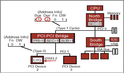
Note that while addresses are not known after reset, bus number and device number are functions of the board layout and ARE known. TwoConfiguration Cycle TypesAs PCI configuration cycles travel downstream, there are two variants: type 0 and type 1. The type is indicated in the lowest two bits of the 32-bit PCI address. Having two types is necessary because PCI devices don't know their bus number or device numbers and must depend on upstream bridges to help select them. Type 1 Cycle Until Target Bus Is ReachedStarting at the host bridge, a type 1 configuration cycle is propagated downstream until it reaches the bridge with a secondary bus number equal to that of the configuration cycle bus number field. Type 1 configuration cycles are ignored by all devices except bridges which will claim them and pass them on to the next downstream bus if the bus number field of the configuration cycle is between the values programmed in the bridge's secondary and subordinate bus number registers. Target Bus Bridge: Convert To Type 0; Assert IDSELThe bridge owning the target secondary bus (based on the value programmed in its secondary bus number register) will convert the type 1 configuration cycle to a type 0. It will also check the device number field and assert the corresponding PCI IDSEL signal to the intended target; IDSEL acts as an explicit target device "chip select". There is a separate IDSEL signal for each device on a PCI bus; a target which detects IDSEL asserted at the same time a Configuration Read or Write cycle (type 0) occurs claims the transaction and uses the remaining information ( Function number and Dword offset ) to access its configuration space. Note: In many systems, the IDSEL signals routed to each device are actually upper bits on the AD bus which are otherwise unused in type 0 configuration cycle address phases. An Example: A PCI Configuration Space AccessFigure 13-1 on page 310 illustrates the use of type 0 and type 1 cycles; in this example, assume the CPU is accessing Dword 1 in the configuration space of Function 0, Device 2, on PCI Bus 1 Figure 13-1. PCI Type 1 and Type 0 Configuration Cycles Events In PCI Configuration Space Example (see Figure 13-1)
|
EAN: 2147483647
Pages: 182