Wiring Up
| Your neatly arranged front panel full of sharp-looking controls and indicators won't do you much good if you don't connect the wires in your diagram to create some action in your program. The following sections detail everything you need to know about wiring techniques.
Remember, wiring is always done on the block diagram, not the front panel.
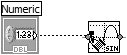
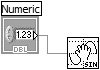
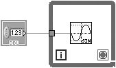
Wiring Tool You use the Wiring tool to connect terminals. The cursor point or "hot spot" of the tool is the tip of the unwound wire segment, as shown. To wire from one terminal to another, click the Wiring tool on the first terminal, move the tool to the second terminal, and then click on the second terminal. It does not matter which terminal you click on first. The terminal area blinks when the hot spot of the Wiring tool is correctly positioned on the terminal, as shown in Figure 4.33. Clicking connects a wire to that terminal. Figure 4.33. Wiring a numeric control's terminal to the input terminal of the Sine function Once you have made the first connection, LabVIEW draws a wire as you move the cursor across the diagram, as if the wire were reeling off the spool. You do not need to hold down the mouse button. To wire from an existing wire, perform the operation described previously, starting or ending the operation on the existing wire. The wire blinks when the Wiring tool is correctly positioned to fasten a new wire to the existing wire. Automatic Wire RoutingIt can be a lot of work to weave your wires in between objects that lay between your wire source and destination. To make this task easier, the LabVIEW Automatic Wire Routing feature automatically finds the best route for wires as you wire them, optimally routing the wire to decrease the number of bends in the wire (see Figure 4.34). You can temporarily disable automatic wire routing by pressing the <A> key after you start a wire. Pressing the <A> key will re-enable automatic wire routing. Also, you can clean up existing wires by right-clicking on a wire and selecting Clean Up Wire from the shortcut menu to automatically route them. Figure 4.34. A wire automatically routing itself around object, with automatic wire routing enabled Some people find automatic wire routing annoying, not unlike Microsoft Word's auto-format features. If you want to disable automatic wire routing by default, you can do so under the LabVIEW options (uncheck the option at Tools>Options>>Block Diagram>>"Enable automatic wire routing"). Automatic WiringAnother way you can wire functions is to use LabVIEW's automatic wiring feature. When you select a function from the Controls palette, you will notice that as you drag it over the block diagram, LabVIEW draws temporary wires to show you valid connections. If you drag the control near a terminal or other object that has a valid input or output, you'll notice LabVIEW connects the two (see Figure 4.35). Releasing the mouse button at this point "snaps" the wiring into place. Figure 4.35. Automatic wiring
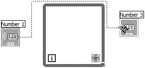
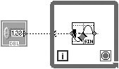
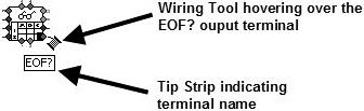
For auto-wiring to work, you will need to drag the function very, very close to the other object you are trying to wire it to. If the automatic wiring seems awkward or doesn't work for you, don't worry about itjust stick to "manual" wiring. You can wire directly from a terminal outside a structure to a terminal within the structure using the basic wiring operation (you'll learn more about structures in Chapter 6, "Controlling Program Execution with Structures"). LabVIEW creates a tunnel where the wire crosses the structure boundary, as shown in Figures 4.36 and 4.37. Figure 4.36 shows what the tunnel looks like as you are drawing the wire; Figure 4.37 depicts a finished tunnel. Figure 4.36. A wire as it is drawn from an object outside a structure to an object inside a structure, before the wire is connected Figure 4.37. A wire that was drawn from an object outside a structure to an object inside a structure, which has a tunnel where the wire passes through the structure wall Wiring Complicated ObjectsWhen you are wiring a complicated built-in node or subVI, it helps to pay attention to the wire "whiskers" and tip strips that appear as the Wiring tool approaches the icon. Wire whiskers, the truncated wires shown around the VI icon in Figure 4.38, indicate the data type needed at that terminal by their style, thickness, and color. Whiskers can be used for the automatic wiring feature we just described. Figure 4.38. Wire "wiskers" and tip strip that appear as the Wiring tool approaches the icon You may also want to take advantage of the Context Help window feature that highlights each connector pane terminal. When you pass the Wiring tool over a terminal, the corresponding Context Help window terminal will blink so that you can be sure you are wiring to the right spot. You can also use the Context Help window to determine which connections are recommended, required, or optional. Bad Wires
When you make a wiring mistake, a broken wirea black dotted line with a red "X" in the middle having arrows on either side indicating the direction of the data flowappears instead of the usual colored wire pattern. Until all such "bad wires" have been vanquished, your run button will appear broken and the VI won't compile.
Whether or not a red X is shown on broken wires is a configurable option. To change this setting, open the Tools>>Options menu, select Block Diagram from the top pull-down menu, and change the value of the Show red Xs on broken wires checkbox. You can remove a bad wire by selecting and deleting it. A better method is to obliterate all bad wires at once by selecting Remove Broken Wires from the Edit menu or by using the keyboard shortcut, <control-B> under Windows and <command-B> on the Mac.
Broken wires can sometimes contain a lot of useful informationthey can be broken because of type conflicts that should be fixed, not because the wires need to be removed. Be very careful that you actually want to remove all the broken wires before using the Remove Broken Wires feature. And remember, if you make a mistake, you can use Undo (<ctrl-Z> in Windows, <meta-Z> in Linux, and <command-Z> in Mac OS X) to get the broken wires back.
Sometimes bad wires are mere fragments, hidden under something or so small you can't even see them. In some cases, all you need to do to fix a broken run arrow is Remove Broken Wires. If you don't know why a wire is broken, hover your mouse over the broken wire and a text box will appear describing your problem(s). This text will also be displayed in the Context Help window. You can also click on the broken run button or pop up on the broken wire and choose List Errors. A dialog box will appear describing your problem(s). You can edit broken wires by popping up on the broken wire and choosing Delete Wire Branch, Create Wire Branch, Remove Loose Ends, Clean Up Wire, Change to Control, Change to Indicator, Enable Indexing at Source, and Disable Indexing at Source to correct the broken wire. Which of these options are available depends on the reason the wire is broken. This procedure is for removing bad wires. If you have very bad and totally evil wires, then you must reboot your computer (just kidding!). Wiring TipsThe following tips may make wiring a little easier for you:
Create two numeric controls on a front panel and wire them to the inputs of the Add function. Don't wire the output just yet. Wire StretchingYou can move wired objects individually or in groups by dragging the selected objects to the new location using the Positioning tool. Wires connected to the selected objects stretch automatically. If you duplicate the selected objects or move them from one diagram or subdiagram into another (for example, from the block diagram into a structure subdiagram such as a While Loop), LabVIEW leaves behind the connecting wires, unless you select them as well. Wire stretching occasionally creates wire stubs or loose ends. You must remove these manually or by using the Remove Broken Wires command from the Edit menu (or the keyboard shortcut) before the VI will execute. Now move the Add function with the Positioning tool and watch how the attached wires adjust. Selecting and Deleting Wires
Positioning Tool A wire segment is a single horizontal or vertical piece of wire. The point at which three or four wire segments join is a junction. A bend in a wire is where two segments join. A wire branch contains all the wire segments from junction to junction, terminal to junction, or terminal to terminal if there are no junctions in between. One mouse click with the Positioning tool on a wire selects a segment. A double-click selects a branch. A triple-click selects an entire wire. Press the <delete> or <backspace> key to remove the selected portion of wire. Select and delete one of your wires; then rewire it. Moving Wires
Positioning Tool You can reposition one or more segments by selecting and dragging them with the Positioning tool. For fine tuning, you can also move selected segments one pixel at a time by pressing the arrow keys on the keyboard. LabVIEW stretches adjacent, unselected segments to accommodate the change. You can select and drag multiple wire segments, even discontinuous segments, simultaneously. When you move a tunnel, LabVIEW normally maintains a wire connection between the tunnel and the wired node. Move a wire segment first using the Positioning tool, and then the arrow keys. Wiring to Off-Screen AreasIf a block diagram is too large to fit on the screen, you can use the scroll bars to move to an off-screen area and drag whatever objects you need to that area. Dragging the Wiring tool slightly past the edge of the diagram window while you are wiring automatically scrolls the diagram (pressing shift will accelerate the scrolling). You can also click in empty space with the Positioning tool and drag outside the block diagram, and more space will be created. Adding Constants, Controls, and Indicators AutomaticallyInstead of creating a constant, control, or indicator by selecting it from a palette and then wiring it manually to a terminal, you can pop up on the terminal and choose Create>>Constant, Create>>Control, or Create>>Indicator to automatically create an object with an appropriate data type for that terminal. The new object will be automatically wired for you, assuming that makes sense. Remember this feature as you develop your programs, because it's amazingly convenient! Create an indicator to display the results of your Add by popping up on the function and selecting Create>>Indicator. LabVIEW will create an indicator terminal wired to the Add output on the block diagram as well as a corresponding front panel indicator, saving you the effort. |


EAN: 2147483647
Pages: 294
- Structures, Processes and Relational Mechanisms for IT Governance
- Integration Strategies and Tactics for Information Technology Governance
- A View on Knowledge Management: Utilizing a Balanced Scorecard Methodology for Analyzing Knowledge Metrics
- Governance in IT Outsourcing Partnerships
- The Evolution of IT Governance at NB Power