Automatically Creating a SubVI from a Section of the Block Diagram
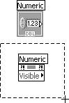
| One key to writing your program right the first time with the least amount of bugs is modularity. The modules in LabVIEW are, of course, subVIs. When you're writing a large application, it's essential to break up the tasks and assign them to subVIs. If you didn't plan ahead (which is by far the best approach) or if the scope of the project increases unexpectedly (never happens), LabVIEW provides a nice recovery mechanism. The Edit>>Create SubVI menu option makes converting sections of your block diagram into subVIs much simpler. If you're working on some code and decide you should make part of it a subVI, no problem! Select the section of a VI's block diagram, as shown in Figure 15.77, and choose Edit>>Create SubVI. LabVIEW converts your selection into a subVI and automatically creates controls and indicators for the new subVI. The subVI replaces the selected portion of the block diagram in your existing VI, and LabVIEW automatically wires the subVI to the existing wires, as shown in Figure 15.78. You'll probably want to add a few features and move a few terminals around to match the wiring elsewhere in your project and, of course, there are terminal descriptions to add, but LabVIEW has given you a good start. This feature is also an excellent option to use, for example, if you need to repeat part of your block diagram in another VI. If two places need the same code, shouldn't it be in a subVI? Figure 15.77. Selecting a block of code, which you wish to convert into a subVI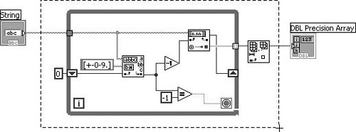 Figure 15.78. The subVI that replaced your selected block of code after selecting Edit>>Create SubVI from the menu
As with all menu options, you can create a custom shortcut key for the Create SubVI command in the Menu Shortcuts section of the Tools>>Options . . . dialog, as we discussed earlier. Despite how easy it is to use, let's look at some rules for using the Create SubVI option.
Because converting some block diagrams into subVIs would change the behavior of your program, there are some instances where you cannot use this feature. These potential problems are listed next.
The Create SubVI option can be a really handy tool in cases where you start with what you thought was a small project (hah!), and you soon realize your program is going to be more complex than you originally thought. However, don't just squeeze a bunch of diagram mess into a subVI to increase your workspacesubVIs should always have a clear, well-defined task. When considering whether to make a part of your diagram a subVI, you might ask yourself, "Could I ever use this piece of code or function somewhere else?" We'll come back to subVIs and modular programming again in Chapter 17, where we look at good programming techniques. |


EAN: 2147483647
Pages: 294
- Using SQL Data Manipulation Language (DML) to Insert and Manipulate Data Within SQL Tables
- Understanding SQL Transactions and Transaction Logs
- Using Data Control Language (DCL) to Setup Database Security
- Understanding Transaction Isolation Levels and Concurrent Processing
- Monitoring and Enhancing MS-SQL Server Performance