Connecting Your Computer to Instruments
| You've got a good a PC and a lab full of instruments that you are excited to control using LabVIEW. What next? Well, the first step is to know how you are going to communicate with your instruments. Are they GPIB, Ethernet, or serial? Most instruments support one, if not several, of these communication methods. Using a GPIB ControllerA GPIB controller is a piece of hardware used to control and communicate with one or more external instruments that have the GPIB interface (see Figure 12.1). The General Purpose Interface Bus, invented by Hewlett-Packard (HP) in the l960s, became the most popular instrument communications standard for many decades. All HP (now Agilent) instruments support it, as well as thousands of others. GPIB was also updated and standardized by the IEEE, and was duly named IEEE 488.2. Some nice features about GPIB are the following:
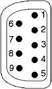
Figure 12.1. GPIB controllers are usually used to communicate with external bench-top instruments, such as oscilloscopes. (Image Copyright Tektronix, Inc. All Rights Reserved. Reprinted with permission.)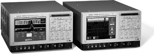 You can obtain a GPIB controller for almost every platform and bus, as well as external interfaces that will convert your serial port, parallel port, Ethernet connection, or USB port to GPIB (see Figure 12.2). Figure 12.2. GPIB controller devices come in many different interface flavors: PCI, PC Card, Ethernet, USB, PXI, and so on.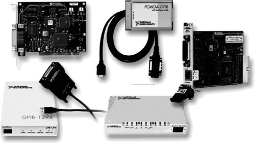 Another feature that makes GPIB popular is that the computer and instrument talk to each other using simple, intuitive ASCII commands using the SCPI protocol, as described later in the section, "SCPI, the Language of Instruments." A multitude of GPIB instrument drivers (LabVIEW VIs for controlling the instruments, which we will learn about later in the section, "Instrument Drivers") available free of charge, make communication with an external instrument as simple as using a few subVls that do all the ASCII commands for you. Installing a GPIB board is usually pretty straightforward. The GPIB boards from NI integrate with NI-MAX so that you can easily configure them under the Devices and Interfaces tree. The best advice is to just follow the installation procedures described in the manual that comes with the GPIB board. Getting Ready for Serial CommunicationsSerial communication has the advantage that it's cheap and simple. Most industrial computers have at least one serial port available. However, for laptops and smaller desktops that do not have a built-in serial port, you can purchase an inexpensive USB-to-RS-232 adaptor (sometimes referred to as a "dongle") from companies such as Keyspan, IOGear, and Belkin. These generally provide from one to four RS-232 ports, per adaptor. If you need many serial ports, consider a plug-in RS-232 board that can provide up to 16 RS-232 ports. Even though it is easy to add serial ports to your computer and connect cables to your hardware, it is not always trivial to get the hardware hooked up and communicating correctly. Although popular standards such as RS-232 and RS-485 specify the cabling, connectors, timing, etc., manufacturers of serial devices more often than not abuse and ignore these standardsthe "RS" in RS-232 and RS-485 stands for "Recommended Standard," and the recommendations are not always followed. This means, unfortunately, that you'll need good documentation on the serial port settings from your instrument manufacturer, and more likely than not, will need to "tweak" the serial port settings on your PC. Until all instrument vendors migrate to USB, you will find a lot of RS-232/485 instruments are still out there. If you need to use them, then it will be important to become familiar with your serial instrument, its pinouts, and the parameters it uses, such as baud rate, parity, stop bits, and so on. Serial ports on a PC are referred to as COM1, COM2, and so on. You can see what serial ports are available on your computer, and how they are configured, by going to Measurement & Automation Explorer (MAX) and clicking on Devices and Interfaces>> Ports. Figure 12.3 shows a PC with two serial ports (COM1 and COM3), as well as a parallel port. Figure 12.3. MAX showing serial ports configured on a PC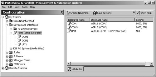 In MAX, you can configure serial ports settings such as the baud rate, stop bits, and so on. On the hardware side, it is very helpful to know what the different lines of a serial port are for. For example, it is not uncommon to build a custom serial cable. Also, some off-the-shelf cables do not have conductors for all the pins on the connectors. You will often need to "Ohm out" (perform a continuity test on) the cable to test the connections between pins on opposite ends of the cable. Figure 12.4 shows the serial pins on a DB-9 connector, the most common serial port configuration. Figure 12.4. PC serial pinout (DB-9 connector) and pin signal assignments
In many cases, only a few of the lines are used. Chances are you'll end up using the following or fewer:
If you experience problems getting your serial device to communicate, try a few of these things:
A handy way to know if your PC is set up correctly for serial communication is to connect two of its serial ports together using a null modem cable (or a regular cable plus a null modem adaptor). If you don't have two serial ports, you can add more ports using USB-to-RS232 dongles. Then, with a dumb terminal program (for example, HyperTerminal on Windows), you can verify that the data you type on one screen appears on the other and vice versa. Another cool trick is to use two virtual serial portsa pair of emulated serial ports that are connected (in software) by an imaginary null modem cable. There are several companies that sell virtual serial port software for a variety of operating systems. Ethernet-Enabled InstrumentsThere are many instruments that have Ethernet ports and can be plugged into your network. They communicate using TCP/IP as the transport mechanism for the commands. Ethernet-enabled instruments are becoming popular and will continue to become more common, as time goes by (see Figure 12.5). Figure 12.5. Ethernet-Enabled Tektronix TDS 1012 Digital Storage Oscilloscope (Image Copyright Tektronix, Inc. All Rights Reserved. Reprinted with permission.)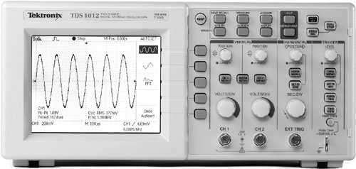 Communicating with an Ethernet-enabled instrument is easy. As we will learn in the section, "VISA Resource Strings," you can address them in software using the following VISA resource string format: TCPIP::host address[::LAN device name][::INSTR] For example, if your device has an IP address of 10.0.1.124, and the instrument device is "SPX01," your VISA resource string can be either TCPIP::10.0.1.124::INSTR or TCPIP::SPX01::INSTR And that's all there is to it!
The LAN eXtensions for Instrumentation (LXI) standardan Ethernet-based instrumentation platform proposed by the LXI Consortium (http://www.lxistandard.org)is growing in popularity and industry adoption. It is designed to provide modularity, flexibility, and performance to small- and medium-sized systems in R&D and manufacturing engineering applications for a variety of industries. Due to the ubiquitousness of Ethernet and TCP/IP networks, we expect this standard, or other Ethernet-based standards, to continue to grow in popularity. |

EAN: 2147483647
Pages: 294