Single Entry Point VPN Configurations
Single Entry Point VPNs enable your enterprise to deploy a solution that protects what many consider an increasingly critical element of the network. VPNs allow you to extend your enterprise to the remote user , and as more companies look toward telecommuting , remote sales forces, and partner networks, making their availability becomes increasingly important. Gone are the days when a VPN was a novelty or a convenience; today it s a necessity. Also, synchronized connections are a must. You wouldn t want users to notice that their VPN connection was just transferred to another gateway and have to reestablish all their connections.
Another nice feature is the support for SEP (and MEP) VPNs when dealing with both remote clients and with gateway-to-gateway VPNs.
Gateway Configuration
In Chapter 3, you began looking at the means of configuring a high availability solution. In this section, you ll look at this topic in greater depth. Figure 12.4 is presented here as a memory refresher. It shows you the General window used for cluster configuration. As covered in Chapter 3, this window is used to initially identify the information about the cluster, such as the cluster name and IP address and also to specify the Check Point applications installed. Note that the IP address configured here is the cluster IP address. This will be the common IP (or Virtual IP) of the cluster.
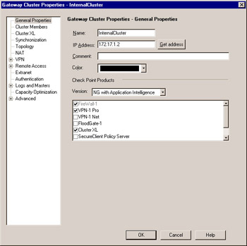
Figure 12.4: Gateway Cluster: General Window
You can use the Topology window (Figure 12.5) to specify which addresses reside behind this cluster. This is similar to the features on a single gateway object s interface properties topology window. One of the most common uses of a manually defined VPN domain is to define an overlapping encryption domain for the gateway cluster for MEP (discussed later).
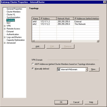
Figure 12.5: Gateway Cluster: Topology Window
If defining the topology manually, you ll first need to define a network object or objects symbolizing the protected network. Then you ll want to define a group object containing each gateway cluster member, as well as the newly created network object. In Figure 12.5, this group is called InternalVPNDomain. Specifying this object on the Topology window is all you need to do to institute a full VPN domain overlap.
In this window you will also be required to define any clustered addresses (VIPs) that will be used in this configuration. If you are using CPHA in legacy mode, these options will not be available since the interfaces with the same IP addresses will automatically be known as shared interfaces. When the interface names on all the cluster members are similar, it makes sense to name the interface name here (which is arbitrary) similar to what the interface name is on each device.
The next window enables you to specify cluster members. Cluster members are the gateways previously defined for inclusion within the cluster. This configuration window is illustrated in Figure 12.6. Note that order is important, as the order that the gateways are listed defines their priority. The order can be shuffled without much effort by the use of the familiar Increase Priority and Decrease Priority sort buttons . Also, new gateways can be added and old ones simply removed, as well. In this case, the Edit button will open the Properties window for the selected gateway, allowing very handy alteration of its settings information.
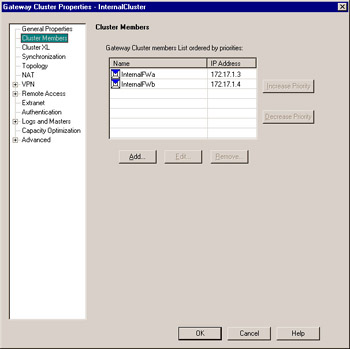
Figure 12.6: Gateway Cluster: Cluster Members
Figure 12.7 shows you how the High Availability or Load Sharing settings are defined. The first options, High Availability and Load Sharing , define whether the cluster will be operating in an active/standby or active/active configuration. Below the High Availability section, there are two options to define the operating mode: New Mode and Legacy Mode , defined previously in this chapter. Under the Load Sharing section, there are also two options: Multicast Mode and Unicast Mode , also described earlier in this chapter.
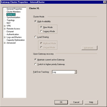
Figure 12.7: Gateway Cluster: ClusterXL Window
When using High Availability, there are two options in the Upon Gateway Recovery section to define how to handle a gateway that has failed but has now returned to the cluster. These are explained below.
-
Maintain current active Gateway In this mode, when a primary gateway has failed and subsequently returned to service, it will not regain control of the cluster. Instead, it will assume the role of secondary and remain in standby. This is useful if you opt not to use state synchronization, as it causes the least interference in these cases.
-
Switch to higher priority Gateway When the primary gateway in the cluster fails and subsequently returns to service, it will retake control of the cluster, assuming that it has been assigned a higher priority (as sorted in the cluster members window).
-
Also defined on this window is the action to take when a failover situation occurs under Fail-Over Tracking , as well as how to share traffic when using load sharing by clicking the Advanced button.
Figure 12.8 shows you the Synchronization window. Synchronization is not required for an HA cluster to function, but it is highly recommended. Synchronization assures that no connections are lost when a failure occurs and connections are migrated to another gateway. It does this by maintaining the state table across all cluster members. This table maintenance has an associated resource cost, which, depending on the size of the state table, can be large. The decision to use this feature is up to you. If you opt for its benefits, you ll need to define a secured network to operate the synchronization over. Note that the network listed in this window will be treated as trusted. The ClusterXL module will trust all messages coming from this network, and, as such, it should be segmented from normal user traffic. If you opt not to use synchronization, simply uncheck the Use State Synchronization field.
Recall from the earlier discussion about state synchronization what the purpose of this mechanism is. Imagine if a user behind your firewall is getting a very large file via File Transfer Protocol (FTP); downloading the newest service pack from Microsoft, for example. If the primary firewall failed and synchronization was enabled, the secondary firewall would take over the connections and the user wouldn t notice the slightest difference. Without synchronization, the transfer would need to be restarted, perhaps with the loss of the already downloaded data.
The remaining tabs of the Gateway Cluster are identical to their cousins in the workstation properties. (Refer back to Chapter 3 for a refresher on the Gateway object.) These allow the setting of the same information as for the individual member workstations, except that here the information is defined per cluster. This also means that the information will no longer be configurable on the individual cluster members.
Policy Configuration
When you have finished configuring the cluster and assigning all the proper members, you still need to allow the VPN-1/FW-1 service to pass between the cluster members (unless you still have implied rules enabled). As mentioned earlier, it s best to make sure that the synchronization network is trusted completely. This is easily accomplished by simply not connecting that network to any other machines. You certainly wouldn t want others synching up with your firewalls ”that could lead to very bad things.
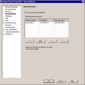
Figure 12.8: Gateway Cluster: Synchronization
Not only are these cluster and VPN configurations useful for perimeter gateways, but also for internal networks when internal networks must be secured and users must secure communications to certain servers. With the proliferation of worms and other fast-propagating attacks, the deployment of internal security measures has become more important and more widely deployed.