Section 8.4. Building the Budget PC
8.4. Building the Budget PCFigure 8-1 shows the components of the budget PC. The ASRock K8NF4G-SATA2 motherboard is at the left front, with the Seagate Barracuda 7200.9 hard drive and the NEC ND-3550A DVD writer front and center. At the right are the AMD Sempron 3100+ processor, the Crucial 512 MB DIMM, and the Arctic Cooling Silencer 64 Ultra CPU cooler, with the Antec SLK1650B case backing everything up. Figure 8-1. Budget PC components, awaiting construction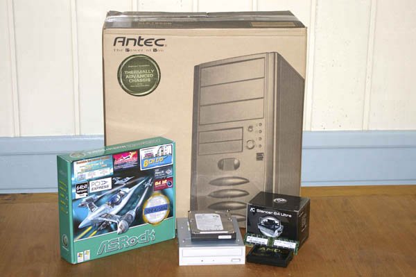 Before you proceed, make sure you have everything you need. Open each box and verify the contents against the packing list. Once you're sure everything is present and accounted for, it's time to get started. 8.4.1. Preparing the CaseAntec must get a lot of support calls from people wondering why the SLK1650B rear fan isn't running. They stuck a warning label on the back of the power supply, shown in Figure 8-2, to tell people that the fan runs only when necessary. Unfortunately, they applied that label before they installed the power supply in the case, leaving part of the label clamped into place by the power supply. For the time being, just rip the label off. We'll remove the remnants of paper later. Figure 8-2. Antec warning that the rear case fan runs only when needed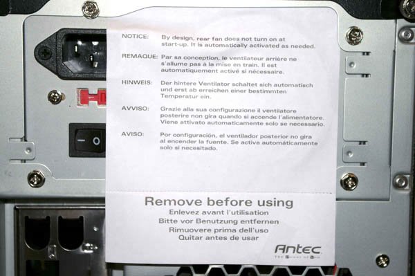
The first step in building any system is always to make sure that the power supply is set to the correct input voltage. Some power supplies set themselves automatically. Others, including the Antec SmartPower 2.0 power supply in this system, must be set manually using a slide switch to select the proper input voltage, as shown in Figure 8-3. Bundled power supplies are nearly always set properly by default, but there are rare exceptions, so it's always a good idea to verify the input voltage setting before you proceed. Figure 8-3. Verify that the power supply is set for the proper input voltage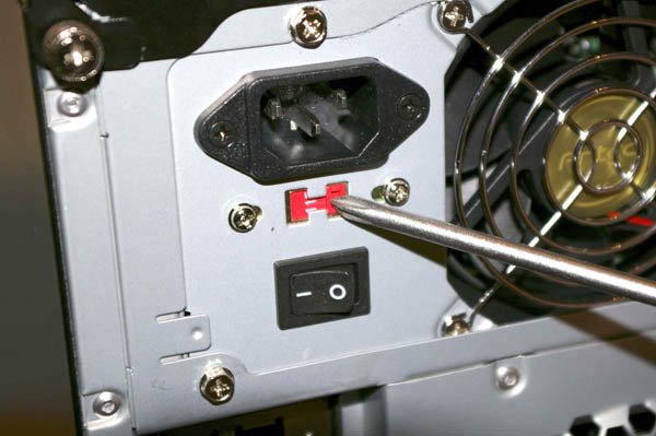
After you've verified that the power supply is set correctly, remove the two thumbscrews that secure the top panel, as shown in Figure 8-4. Figure 8-4. Remove the thumbscrews that secure the top panel After you remove the thumbscrews, slide the top panel slightly toward the rear, as shown in Figure 8-5, and then lift it off, as shown in Figure 8-6. Figure 8-5. Slide the top panel to the rear to release it Figure 8-6. Lift the top panel off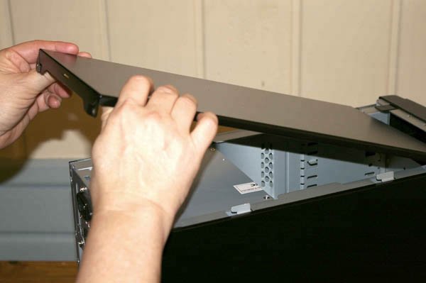 With the top panel removed, tilt the left side panel down and remove it, as shown in Figure 8-7. Be careful not to damage the TAC shroud, which is the black plastic duct attached to the side panel. Remove the right side panel in the same manner. Put the top and side panels safely aside, where they won't be scratched while you are building the system. Figure 8-7. Remove the side panels and set them safely aside With the power supply exposed, it's time to remove the remnants of the Antec warning label we mentioned earlier, shown in Figure 8-8. To do so, remove the four screws that secure the power supply, and slide the power supply slightly forward. Remove the paper scraps, slide the power supply back into position, and reinsert the four screws to secure it. Figure 8-8. Remove the remnants of the Antec warning label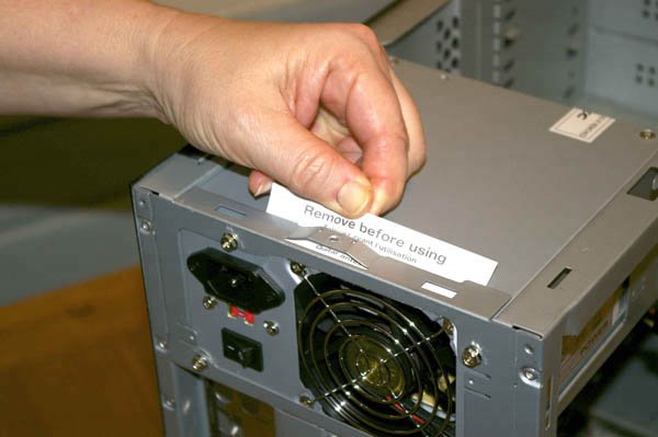 Every case we've ever seen, including the Antec SLK1650B, comes with an I/O template. So does every motherboard. The generic I/O template supplied with the case never seems to fit the I/O panel of the motherboard, so you need to remove the stock I/O template and replace it with the one supplied with the motherboard. I/O templates are made of thin metal that is easily bent. The best way to remove an I/O template without damaging it, as shown in Figure 8-9, is to use a tool handle to press gently against the panel from outside the case, while using your fingers to support the panel from inside the case. (We don't know why we care about damaging the generic I/O template supplied with the case. We have a stack of them sitting around, and have never needed one.) Figure 8-9. Remove the I/O template supplied with the case Most motherboards, including the ASRock K8NF4G-SATA2, come with a custom ATX I/O template designed to match the motherboard I/O panel. Before you install the custom I/O template, compare it to the motherboard I/O panel to make sure the holes in the template correspond to the connectors on the motherboard. Once you've done that, press the custom I/O template into place. Working from inside the case, align the bottom, right, and left edges of the I/O template with the matching case cutout. When the I/O template is positioned properly, press gently along the edges to seat it in the cutout, as shown in Figure 8-10. It should snap into place, although getting it to seat properly sometimes requires several attempts. It's often helpful to press gently against the edge of the template with the handle of a screwdriver or nutdriver. Figure 8-10. Snap the custom I/O template into place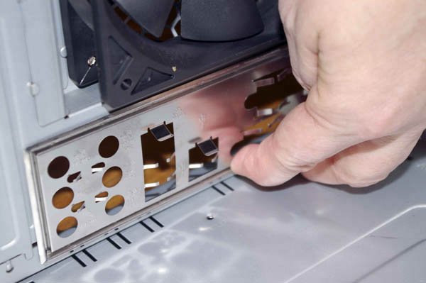
After you install the I/O template, carefully slide the motherboard into place, making sure that the back-panel connectors on the motherboard are firmly in contact with the corresponding holes on the I/O template. Compare the positions of the motherboard mounting holes with the standoff mounting positions in the case. One easy method is to place the motherboard in position and insert a felt-tip pen through each motherboard mounting hole to mark the corresponding standoff position beneath it.
The ASRock K8NF4G-SATA2 motherboard has six mounting holes. Many cases are shipped with several standoffs already installed. The Antec SLK1650B has only one standoff preinstalled, which happens to be in one of the positions required by the ASRock K8NF4G-SATA2 motherboard. That means we needed to install standoffs in the five remaining positions required by the motherboard. Install additional brass standoffs until each motherboard mounting hole has a corresponding standoff. Although you can screw in the standoffs using your fingers or needle-nose pliers, it's much easier and faster to use a 5mm nutdriver, as shown in Figure 8-11. Tighten the standoffs finger-tight, but do not overtighten them. It's easy to strip the threads by applying too much torque with a nutdriver. Figure 8-11. Install a brass standoff in each mounting position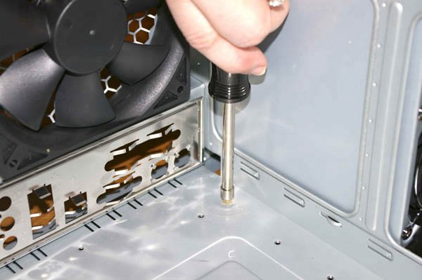 Once you've installed all the standoffs, do a final check to verify that (a) each motherboard mounting hole has a corresponding standoff, and (b) that no standoffs are installed that don't correspond to a motherboard mounting hole. As a final check, we usually hold the motherboard in position above the case, as shown in Figure 8-12, and look down through each motherboard mounting hole to make sure there's a standoff installed below it. Figure 8-12. Verify that a standoff is installed for each motherboard mounting hole and that no extra standoffs are installed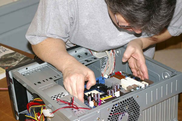
8.4.2. Preparing and Populating the MotherboardIt is always easier to prepare and populate the motherboardinstall the processor and memorywhile the motherboard is outside the case. In fact, you must do so with some systems, because installing the heatsink/fan unit requires access to both sides of the motherboard. Even if it is possible to populate the motherboard while it is installed in the case, we always recommend doing so with the motherboard outside the case and lying flat on the work surface. More than once, we've tried to save a few minutes by replacing the processor without removing the motherboard. Too often, the result has been bent pins and a destroyed processor.
8.4.2.1. Preparing the motherboardWe decided to install an inexpensive third-party CPU cooler, because we wanted a cooler that was quieter and more efficient than the stock AMD cooler. We'd used the $13 Arctic Cooling Silencer 64 Ultra, shown in Figure 8-13, on several earlier systems, and were pleased with its noise level and cooling performance. We also considered using the Arctic Cooling Silencer 64 UltraTC, which has a temperature-controlled variable-speed fan, but at $20 it was a bit much for our budget. So, without thinking much about it, we ordered an Arctic Cooling Silencer 64 Ultra for this system. Figure 8-13. The Arctic Cooling Silencer 64 Ultra CPU cooler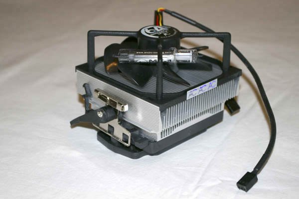 That turned out to be a mistake, because fitting that CPU cooler to the motherboard required some minor surgery. Our first inclination was simply to order a different CPU cooler and let our readers remain ignorant of our mistake. But mistakes can be instructive, so we decided to go ahead and build the system with the Arctic Cooling Silencer 64 Ultra CPU cooler. It wasn't the first time we'd had to do minor surgery on a motherboard to fit a CPU cooler to it, and it won't be the last. But you can avoid all of the hassle simply by choosing a compatible CPU cooler, such as the Spire model we recommended earlier in this chapter. The ASRock motherboard comes with a CPU cooler retaining bracket installed. Presumably, that bracket fits many standard CPU coolers, but it did not fit any of the AMD CPU coolers we had available, including one retail-boxed AMD cooler. The problem was the protruding vertical posts visible in Figure 8-14. Figure 8-14. Lift the white plastic posts to release the standard bracket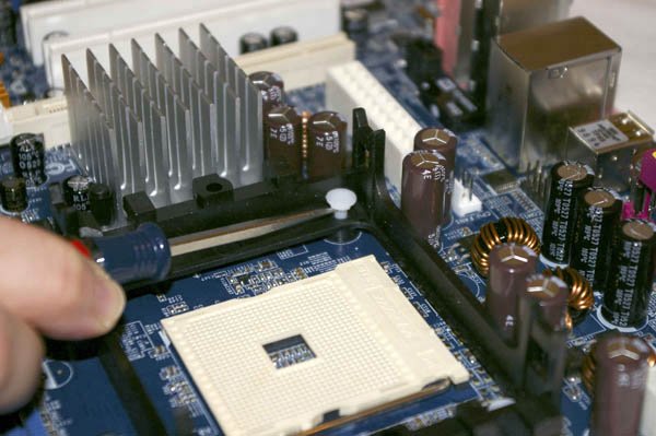 Like many aftermarket CPU coolers, the Arctic Cooling Silencer 64 Ultra comes with its own retaining bracket. To install the Arctic Cooling bracket, you must first remove the bracket supplied with the ASRock motherboard. To do so, use a small flat-blade screwdriver to lift the four white posts, as shown in Figure 8-14. Lifting the posts releases the pressure on the plastic expansion clamps on the underside of the motherboard. After you lift all four posts, pull the retaining bracket straight up to remove it, as shown in Figure 8-15. If the bracket does not pull free easily, use the flat part of the screwdriver blade to press gently on the expansion clamps on the bottom side of the motherboard until they release. Figure 8-15. Lift the retaining bracket straight up to remove it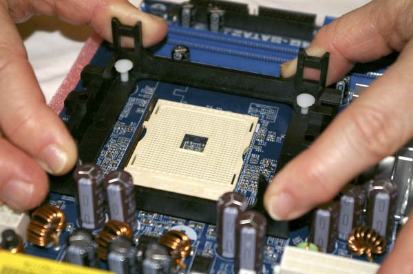 With the standard retaining bracket removed, the four retaining bracket mounting holes are visible, as shown in Figure 8-16, at the four corners of the processor socket. Figure 8-16. With the standard bracket removed, the four mounting holes are visible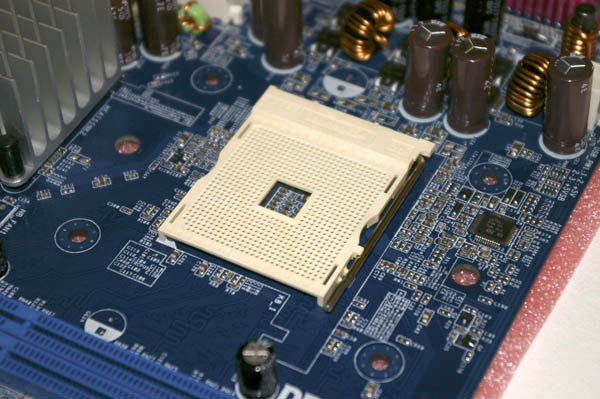 The Arctic Cooling CPU cooler comes with a two-part custom retaining bracket made of heavy plastic. One part is installed on the top of the motherboard, where the heatsink can be clamped to it. The second part is installed beneath the motherboard, to distribute the weight of the heatsink over the processor socket area of the motherboard, rather than putting all of that weight on a couple of screw holes. To begin installing the bracket, remove the two screws that secure the two parts, as shown in Figure 8-17. Figure 8-17. Disassemble the retaining bracket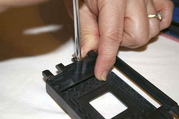 Align the four posts on the bottom of the top portion of the retaining bracket with the corresponding holes in the motherboard, and drop the retaining bracket into place. Align the bottom portion of the retaining bracket under the motherboard, with the screw holes lining up with the corresponding holes in the motherboard. Partially drive one screw, as shown in Figure 8-18, to secure the two parts of the retaining bracket together loosely. Figure 8-18. Partially drive one screw to loosely connect the two parts of the retaining bracket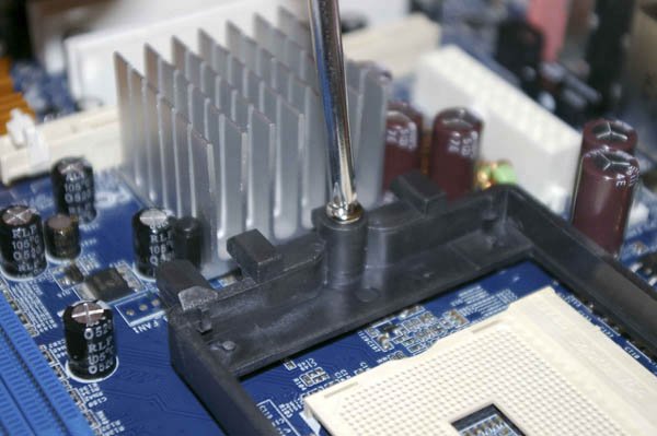 Tilt the motherboard upward, as shown in Figure 8-19, and align the second screw hole in the bottom part of the retaining bracket. Drive the second screw in to align the two parts of the bracket completely, and then finish driving both screws to clamp the bracket tightly into position. Drive both screws in completely, but do not overtighten them. Finger-tight is sufficient. Figure 8-19. Align the bottom portion of the bracket and drive a second screw to secure it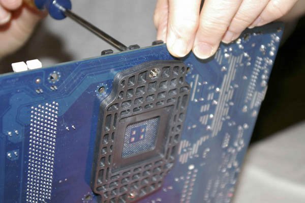 8.4.2.2. Installing the processorTo install the AMD Sempron processor, lift the arm of the ZIF (zero insertion force) socket, as shown in Figure 8-20, until it reaches vertical. With the arm vertical, there is no clamping force on the socket holes, which allows the processor to drop into place without requiring any pressure. Figure 8-20. Lift the socket lever to prepare the socket to receive the processor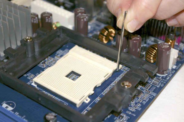 Pin 1 is indicated on the processor and socket by a small triangle. With the socket lever vertical, align pin 1 of the processor with pin 1 of the socket and drop the processor into place, as shown in Figure 8-21. The processor should seat flush with the socket just from the force of gravity, or at most with the slightest fingertip pressure. If the processor doesn't seat easily, something is misaligned. Remove the processor and verify that it is aligned properly and that the pattern of pins on the processor corresponds to the pattern of holes on the socket. Never apply any significant pressure to the processor. You'll bend one or more pins, destroying the processor. Figure 8-21. Dropping the processor into place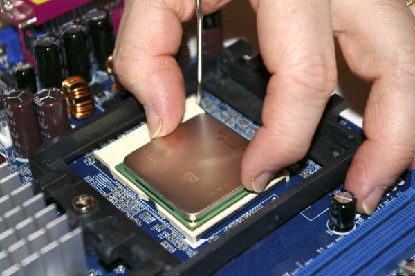 With the processor in place and seated flush with the socket, press the lever arm down and snap it into place, as shown in Figure 8-22. You may have to press the lever arm slightly away from the socket to allow it to snap into a locked position. Closing the ZIF lever may cause the processor to lift slightly out of its socket. Once you are sure the processor is fully seated, it's safe to maintain gentle finger pressure on the processor if necessary to keep it fully seated as you close the ZIF lever. Figure 8-22. Locking the processor into the socket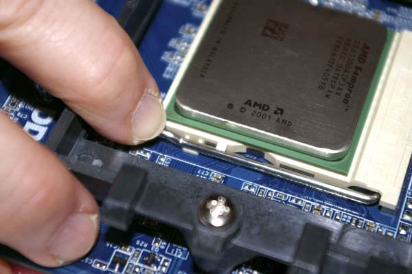 8.4.2.3. Installing the CPU coolerModern processors draw as much as 130W of power and must dissipate that power as heat over the surface of their heat spreaders, which are about the size of a large postage stamp. Without a good CPU cooler, also called a heatsink/fan (HSF) unit, the processor would immediately shut itself down to prevent damage from overheating. Our Sempron 3100+ has a design thermal power of only 62W, but even that relatively low wattage produces considerable waste heat. Like all microATX motherboards, the ASRock K8NF4G-SATA2 crams in many components with very little clearance. The small size of microATX motherboards means they have to make a lot of compromises in where to position components, and it's often problematic to mount the CPU cooler, particularly if it's a third-party model. In this case, the problem was severe, as shown in Figure 8-23. The clamping bracket on the CPU cooler intruded into the space used by the northbridge heatsink, visible at the lower right of the image as a finned aluminum assembly. Some CPU coolers use a cammed clamping lever on only one side of the cooler, with a simple metal bracket on the other side. The Arctic Cooling CPU cooler uses two clamping levers, one on either side of the cooler, so we couldn't simply reverse the cooler to avoid the problem. Figure 8-23. The CPU cooler cannot be seated fully because the northbridge heatsink interferes
Donning our kamikaze headband, we began by removing the northbridge heatsink. To do that, we used our needle-nose pliers to release the two expanding clamping posts that secure the northbridge heatsink to the motherboard, as shown in Figure 8-24. Figure 8-24. Release the northbridge heatsink clamping posts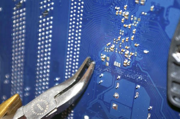 As you squeeze the posts gently, press them toward the motherboard until they pop free. At that point, the northbridge heatsink is still loosely connected to the northbridge chip by thermal compound. Pull up gently on the heatsink until it comes free. The northbridge chip is exposed, as shown in Figure 8-25, and there is now enough clearance to install the CPU cooler. Figure 8-25. The exposed northbridge chip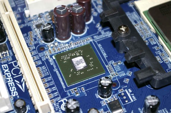
We're now ready to install the CPU cooler. To begin, use a paper towel or soft cloth to polish the CPU heat spreader, as shown in Figure 8-26. The goal is to remove any grease, grit, or other material that might prevent the heatsink from making intimate contact with the processor surface. Figure 8-26. Polish the CPU heat spreader to remove any foreign material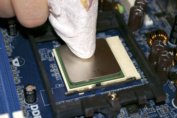 After you polish the CPU, check the surface of the heatsink. If the heatsink base is bare, as is true of the Arctic Cooler model we used, that means it's intended to be used with thermal compound, sometimes called "thermal goop." In that case, also polish the heatsink base, as shown in Figure 8-27. Some heatsinks have a square or rectangular pad made of a phase-change medium, which is a fancy term for a material that melts as the CPU heats and resolidifies as the CPU cools. This liquid/solid cycle ensures that the processor die maintains good thermal contact with the heatsink. If your heatsink includes such a pad you needn't polish the base of the heatsink. (Heatsinks use either a thermal pad or thermal goop, not both.) Figure 8-27. Polish the base of the CPU cooler heatsink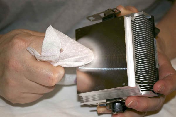
At this point during our actual build, we made a mistake. We used the syringe of thermal compound supplied with the Arctic Cooling CPU cooler (visible in Figure 8-13). That thermal compound turned out to be the most obnoxious we'd ever used. It was dry, excessively tacky, and refused to spread evenly. After making a mess with it, we ended up cleaning it all off, repolishing the CPU heat spreader and heatsink, and doing what we should have done originally. We went to our workbench, retrieved our tube of Antec Silver Thermal Compound (shown in Figure 8-28), and applied a small amount to the heat spreader. Figure 8-28. Applying Antec Silver Thermal Compound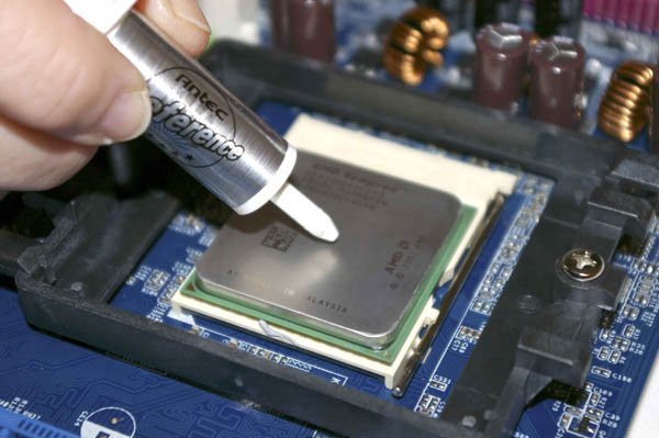 Use your finger to spread the thermal compound evenly over the surface of the heat spreader, as shown in Figure 8-29. (We've always found thermal compound to be harmless, but if you're nervous about it, you can use a talc-free rubber glove or plastic wrap between your finger and the compound.) The goal is to use just enough thermal compound to provide a thin, even layer over the entire surface of the heat spreader. Remove any excess compound before you proceed to the next step. Figure 8-29. Spread the thermal compound evenly over the surface of the heat spreader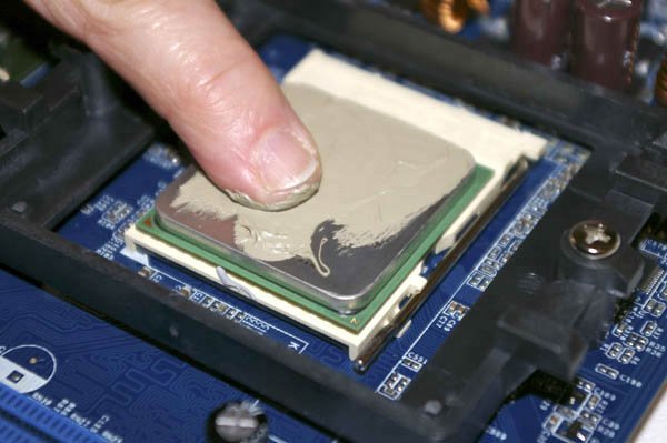 Orient the CPU cooler above the processor, as shown in Figure 8-30, keeping it as close to horizontal as possible. Slide the CPU cooler down into the retaining bracket. Press down gently and use a small circular motion to spread the thermal goop evenly over the surface of the processor. Figure 8-30. Insert the CPU cooler into the retaining bracket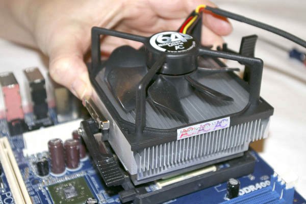
With the CPU cooler resting loosely in place, the next step is to clamp it tightly against the processor to ensure good thermal transfer between the CPU and heatsink. To do so, hold the metal retaining bracket in place, as shown in Figure 8-31, while you press down the cammed locking lever with the other hand until the clamp locks into place. Make sure that all three of the plastic protrusions have engaged the holes in the bracket. Repeat this step for the second locking lever. With both levers locked, the CPU cooler is secured firmly and clamped into tight contact with the processor. Figure 8-31. Clamp the CPU cooler into firm contact with the processor The next step is to reinstall the northbridge heatsink. We had hoped to be able to do that without modifying the heatsink, but that turned out to be impossible. In order to clear the locking lever on the CPU cooler, we had to bend some of the northbridge heatsink fins, as shown in Figure 8-32. Fortunately, the fins are made of soft aluminum, which is quite easy to bend with your needle-nose pliers. Figure 8-32. Modify the northbridge heatsink to fit by bending one set of fins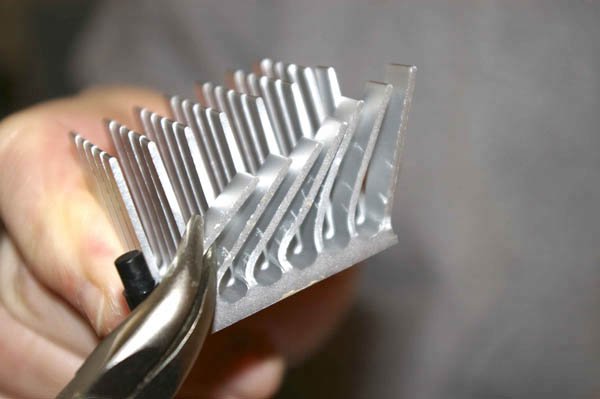 Before you reinstall the northbridge heatsink, you must remove the old thermal pad from the heatsink base and from the northbridge chip itself. Do that by rubbing gently with your thumb to remove the bulk of the thermal pad, and then polishing gently with a paper towel. If the thermal pad material is difficult to remove, use your fingernail to peel it off the surface of the heatsink and northbridge chip. Apply a thin layer of thermal compound to the northbridge chip and spread it evenly. Place the northbridge heatsink in position, as shown in Figure 8-33, rotate it slightly to spread the thermal compound evenly, and then press the two locking posts back into place to secure the heatsink. Figure 8-33. Replace the northbridge heatsink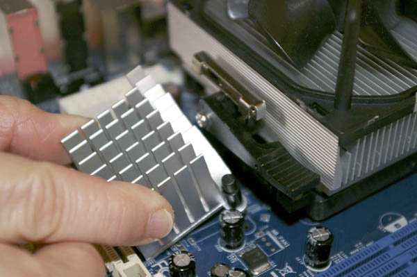 Figure 8-34 shows the northbridge heatsink reinstalled, with the bent fins clearing the CPU cooler clamping lever. The northbridge heatsink has six rows of fins, so we'd have reduced its cooling efficiency by about 16% if we'd removed one row of fins entirely rather than simply bending them. As modified, we estimate the northbridge cooling efficiency has been reduced by no more than 5%, if that. The fins are still well exposed to the air flow from the rear chassis fan. (When the system is running, the northbridge heatsink fins become noticeably warm to the touch, indicating that they are doing their job well.) Figure 8-34. The modified northbridge heatsink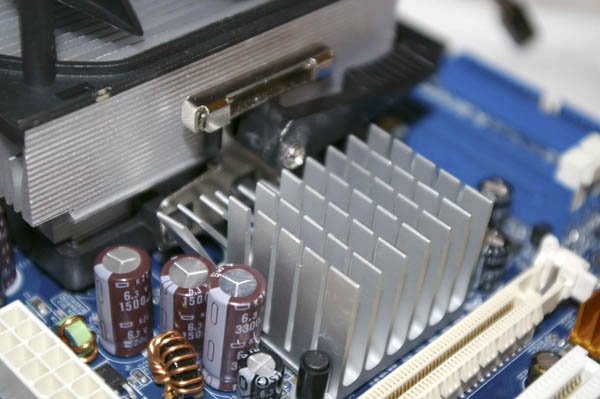 The thermal mass of the CPU cooler heatsink draws heat away from the CPU, but the heat must be dissipated to prevent the CPU from eventually overheating as the heatsink warms up. To dispose of excess heat as it is transferred to the heatsink, most CPU coolers use a fan to continuously draw or push air through the fins of the heatsink. Some CPU fans use a drive power connector, but most are designed to attach to dedicated CPU fan connector on the motherboard. Using a motherboard fan power connector allows the motherboard to control the CPU fan, reducing speed for quieter operation when the processor is running under light load and not generating much heat, and increasing fan speed when the processor is running under heavy load and generating more heat. The motherboard can also monitor fan speed, which allows it to send an alert to the user if the fan fails or begins running sporadically. To connect the CPU fan, locate the 3-pin header connector on the motherboard labeled CPU Fan, and plug the keyed cable from the CPU fan into that connector, as shown in Figure 8-35. Figure 8-35. Connect the CPU fan cable to the CPU fan connector 8.4.2.4. Installing memoryInstalling memory takes only a few seconds. The ASRock motherboard provides two memory slots, but we're installing only one Crucial 512 MB DIMM, leaving the second slot free for later memory expansion. To begin installing the memory, pivot the locking tabs on both sides of both DIMM sockets outward, as shown in Figure 8-36. (We're installing memory in only one socket, but having both sets of locking tabs open makes it easier to ensure that the one DIMM we're installing is properly seated.) Figure 8-36. Pivot the locking tabs on both sides of both DIMM sockets outward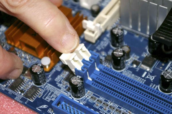 We'll install our DIMM in the first memory slot, which is the one nearer the processor. To install the DIMM, orient it with the notch in the contact area of the DIMM aligned with the raised plastic tab in the slot and slide the DIMM into place, as shown in Figure 8-37, making sure that both ends of the DIMM slide straight into the slots on the locking tab brackets. Figure 8-37. Orient the DIMM with the notch aligned properly with the socket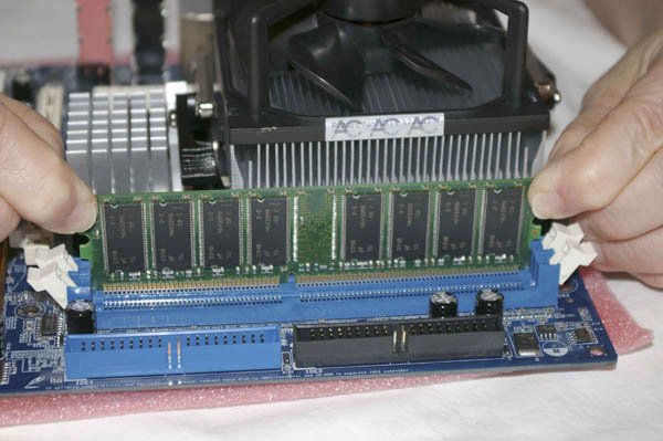 With the DIMM properly aligned with the slot and oriented vertically relative to the slot, use both thumbs to press down on the DIMM until it snaps into place, as shown in Figure 8-38. The locking tabs should automatically pivot back up into the locked position when the DIMM snaps into place. If they don't, make absolutely certain that the DIMM is well seated and then close the locking tabs manually to lock the DIMM into the socket. Figure 8-38. Seat the DIMM by pressing firmly until it snaps into place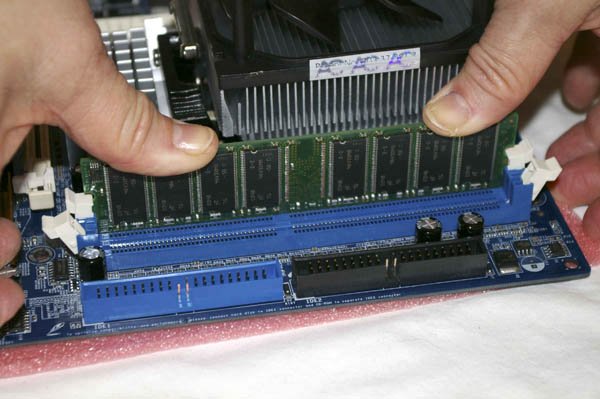 When the DIMM is fully seated, the locking tabs should mate fully with the notches on the DIMM, as shown in Figure 8-39. Figure 8-39. Make sure that the locking tabs on the bracket fully engage the cutouts on the DIMM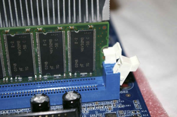 With the processor and memory installed, you're almost ready to install the motherboard in the case. Before you do that, check the motherboard documentation to determine if any configuration jumpers need to be set. The ASRock motherboard requires no additional configuration, so we proceeded to the next step. 8.4.3. Installing the MotherboardInstalling the motherboard is the most time-consuming step in building the system because there are so many cables to connect. It's important to get all of them connected right, so take your time and verify each connection before and after you make it. 8.4.3.1. Seating and securing the motherboardTo begin, slide the motherboard into the case, as shown in Figure 8-40. Carefully align the back-panel I/O connectors with the corresponding holes in the I/O template, and slide the motherboard toward the rear of the case until the motherboard mounting holes line up with the standoffs you installed earlier. Figure 8-40. Slide the motherboard into position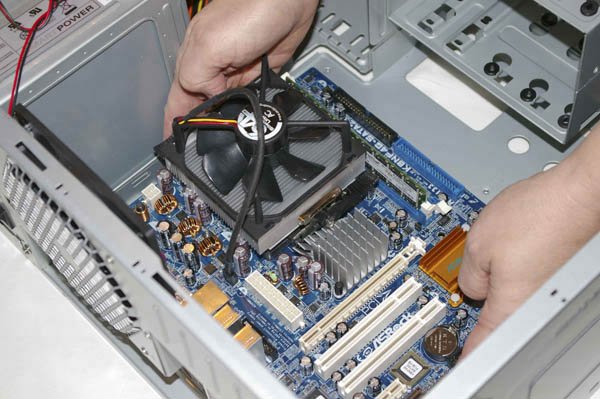 Before you secure the motherboard, verify that the back-panel I/O connectors mate properly with the I/O template, as shown in Figure 8-41. The I/O template has metal tabs that ground the back-panel I/O connectors. Make sure none of these tabs intrude into a port connector. An errant tab at best blocks the port, rendering it unusable, and at worst may short out the motherboard. Figure 8-41. Verify that the back-panel connectors mate cleanly with the I/O template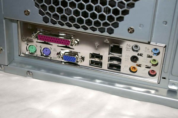
After you position the motherboard and verify that the back-panel I/O connectors mate cleanly with the I/O template, insert a screw through one mounting hole into the corresponding standoff, as shown in Figure 8-42. You may need to apply pressure to keep the motherboard positioned properly until you have inserted two or three screws. Figure 8-42. Install screws in all mounting holes to secure the motherboard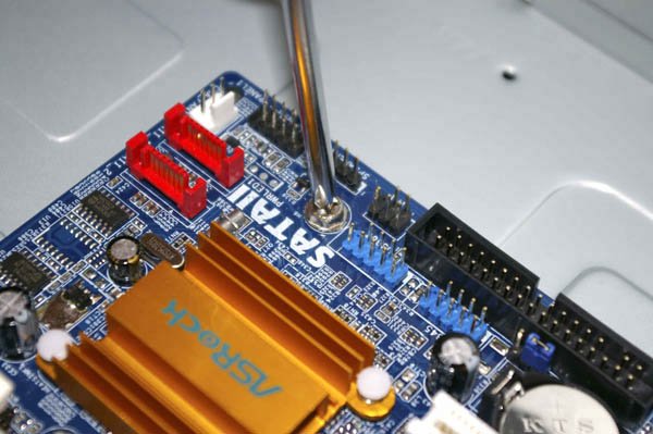 If you have trouble getting all the holes and standoffs aligned, insert two screws in opposite corners but don't tighten them completely. Use one hand to press the motherboard into alignment, with all holes matching the standoffs. Then insert one or two more screws and tighten them completely. Finish mounting the motherboard by inserting screws into all standoffs and tightening them. With first-rate products like the Antec SLK1650B case and the ASRock K8NF4G-SATA2 motherboard, all the holes usually line up perfectly. With cheap products, that's often not true. At times, we've been forced to use only a few screws to secure the motherboard. We prefer to use all of them, both to physically support the motherboard and to make sure all of the grounding points are in fact grounded, but if you can't get all of the holes lined up, simply install as many screws as you can. 8.4.3.2. Connecting front-panel switch and indicator cablesOnce the motherboard is secured, the next step is to connect the front panel switch and indicator cables to the motherboard. Before you begin connecting front panel cables, examine the cables. Each is labeled descriptively, e.g., "POWER SW" and "H.D.D. LED." Match those descriptions with the front panel connector pins on the motherboard to make sure you connect the correct cable to the appropriate pins. Once you determine the proper orientation for each cable, connect it as shown in Figure 8-43. Figure 8-43. Connect the front-panel switch and indicator cables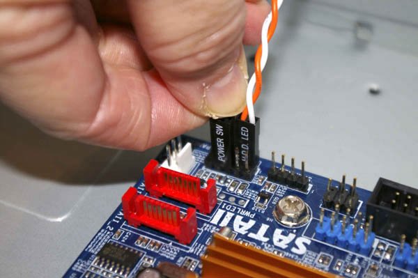
Keep these guidelines in mind as you connect the front-panel cables:
When you're connecting front-panel cables, try to get it right the first time, but don't worry too much about getting it wrong. Other than the power switch cable, which must be connected properly for the system to start, none of the other front-panel switch and indicator cables is essential, and connecting them wrong won't damage the system. 8.4.3.3. Connecting front-panel switch and indicator cablesAfter you connect the front-panel switch and indicator cables to the motherboard, connect the speaker cable, as shown in Figure 8-44. Connect the cable with the signal wire (in this case, red) on pin 1 and the ground wire (black) opposite. If you use a motherboard that has a built-in speaker, there may be no speaker header pins on the motherboard. If so, just leave this cable disconnected. If the motherboard has both a built-in speaker and speaker header pins, we generally connect this cable because the case speaker usually provides better volume than a surface-mounted motherboard speaker. Figure 8-44. Connect the speaker cable 8.4.3.4. Connecting front-panel USB portsThe ASRock K8NF4G-SATA2 motherboard provides four internal USB 2.0 connectors, in two sets of two header pin groups. The Antec SLK1650B case provides two front-panel USB 2.0 ports, which terminate in a single 10-pin USB connector cable. Connect this cable to one of the motherboard USB header pin sets, as shown in Figure 8-45. Figure 8-45. Connect the front-panel USB cable to a USB header pin set on the motherboard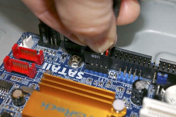 8.4.4. Installing the Hard DriveThe Antec SLK1650B has three external 5.25" drive bays, two external 3.5" drive bays, and three internal 3.5" drive bays. The external bays are for devices like optical drives and floppy disk drives that use removable media, and can also be used for internal hard drives. The three internal 3.5" bays can each hold one hard drive. To begin installing the hard drive, remove the three screws that secure the internal drive bay, as shown in Figure 8-46. Figure 8-46. Remove the screws that secure the internal drive bay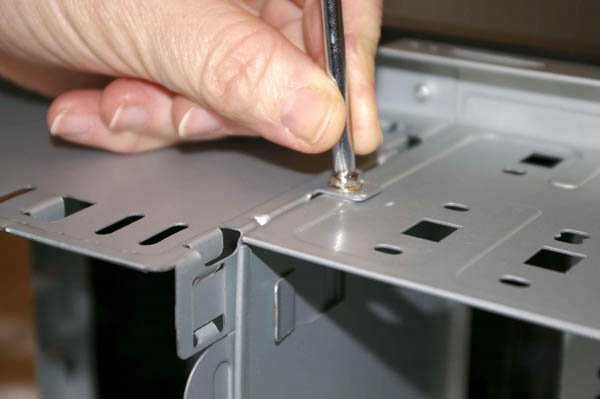 After you remove the three screws, lift the drive bay free of the chassis, as shown in Figure 8-47. Figure 8-47. Lift the internal drive bay free of the chassis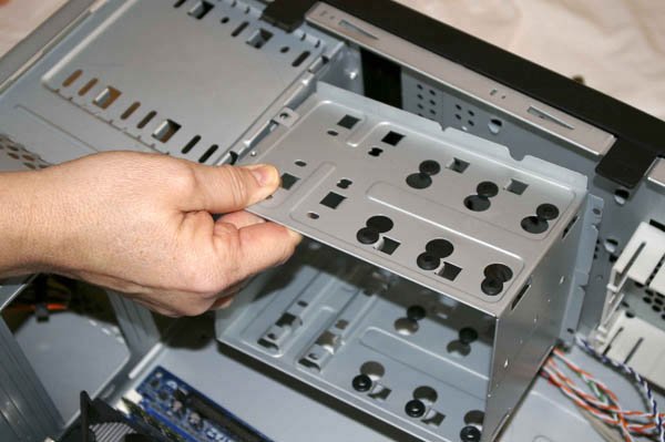
Before you install the hard drive in the drive bay, verify that the drive is configured properly. We are using a Serial ATA hard drive in this system. Serial ATA drives do not require configuration because each S-ATA drive connects to a dedicated interface. If we had used a parallel ATA (P-ATA) hard drive, we'd have checked the jumpers on the drive to verify it was set as Master. The Antec drive bay uses rubber shock-mounting pads to isolate the drive, which reduces the amount of vibration and noise transferred from the hard drive to the chassis. Several of these pads are visible in Figure 8-48, including one under the screw being driven. Secure the drive to the bay by installing four of the provided screws with oversize heads. Drive the screws finger-tight, but do not overtorque them. Figure 8-48. Secure the hard drive to the bay using four of the provided large-head screws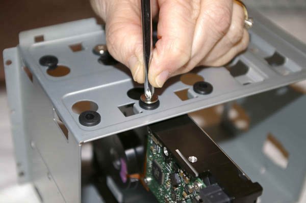 With the hard drive secured in the bay, the next step is to reinstall the bay in the chassis, as shown in Figure 8-49. To do so, align the notches in the drive bay with the chassis tabs and slide the drive bay into the chassis. Figure 8-49. Slide the drive bay into the chassis, aligning the slots in the bay with the tabs on the chassis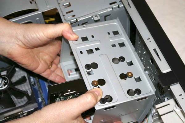 With the drive bay fully seated, reinstall the three screws you removed earlier to secure the drive bay in the chassis, as shown in Figure 8-50. Figure 8-50. Reinstall the three screws you removed earlier to secure the drive bay to the chassis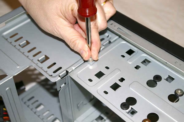 With the drive bay reinstalled, the next step is to connect power to the hard drive. To do so, examine the various cables coming out of the power supply to locate a Serial ATA power cable. The Serial ATA power connector is keyed similarly to the Serial ATA data cable, using a slot and tab arrangement. Align the keying slot on the cable with the keying tab on the drive and slide the power cable into place, as shown in Figure 8-51. Figure 8-51. Connect the Serial ATA power cable to the hard drive The next step is to connect the Serial ATA data cable to the drive. It doesn't matter which end of the Serial ATA cable you connect to the drive. The two ends are interchangeable. The Serial ATA data cable is keyed with a notch at one end that slides over a corresponding tab on the drive connector. Align the cable connector to the drive connector and press firmly until the cable connector slides into place, as shown in Figure 8-52. Figure 8-52. Connect the Serial ATA data cable to the hard drive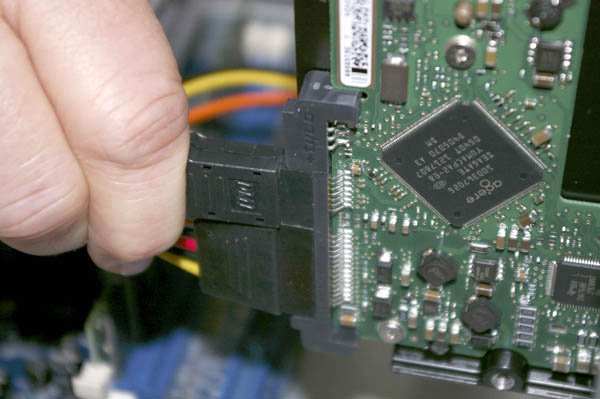
The final step is to connect the Serial ATA data cable to the motherboard Serial ATA interface. The motherboard provides two Serial ATA interfaces, labeled SATA1 and SATA2. Although the drive functions properly connected to either interface, best practice is to connect the primary hard drive to the first interface, which is SATA1. The motherboard SATA connector is keyed in the same fashion as the hard drive SATA connector. Orient the Serial ATA data cable so that its keying slot corresponds to the keying tab on the motherboard connector, and press the cable into place, as shown in Figure 8-53. Figure 8-53. Connect the Serial ATA data cable to the motherboard interface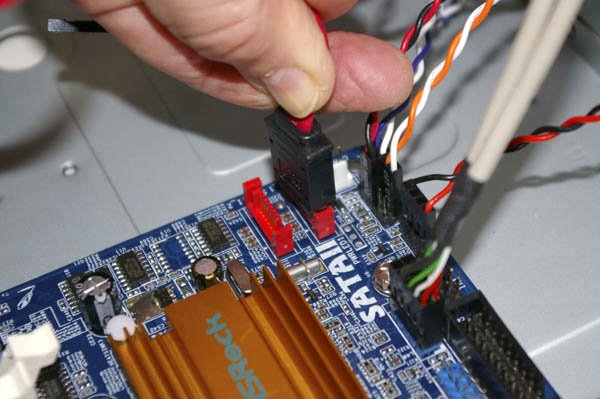 8.4.5. Installing the Optical DriveBefore you install the optical drive, verify the jumper settings. The NEC ND-3550A DVD writer ships with a jumper installed in the rightmost position, as shown in Figure 8-54. This default jumper setting configures the drive as master. We plan to use the optical drive as the master on the primary ATA channel, so the default jumper setting is correct. Figure 8-54. Verify that the optical drive jumper is set to master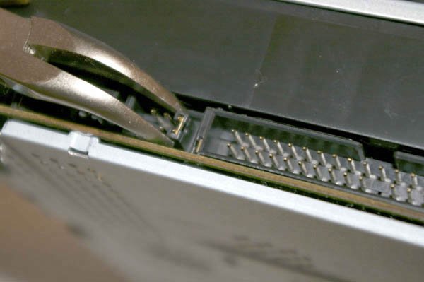
It's usually easier to connect the ATA cable to the drive before you install the drive in the case. The ASRock K8NF4G-SATA2 motherboard comes with an 80-wire Ultra ATA cable, which we used. Because optical drives have relatively slow transfer rates, they can use the older 40-wire ATA cable rather than the 80-wire Ultra-ATA cable used for ATA hard drives. (An 80-wire cable works fine if that's all you have, but it's not necessary.) To connect the cable, locate pin 1 on the drive connector, which is usually nearest the power connector. The pin 1 side of the cable is indicated by a red stripe. Align the cable connector with the drive connector, making sure the red stripe is on the pin 1 side of the drive connector, and press the cable into place, as shown in Figure 8-55. Figure 8-55. Connect the ATA data cable to the optical drive, making sure pin 1 is oriented correctly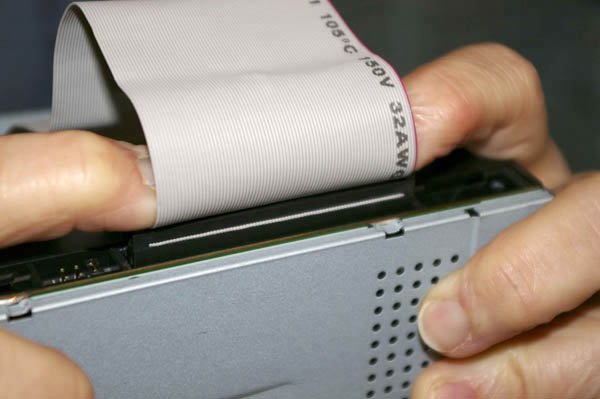 The Antec SLK1650B case provides three external 5.25" bays, each of which is covered by a snap-in plastic bezel. Before installing the drive you have to remove the bezel for the selected drive bay. The easiest way to do that on the Antec case is to press the bezel from behind, as shown in Figure 8-56, until it pops out. The two lower external 5.25" bays have metal RF shields installed, but the upper bay lacks that shield. For simplicity, we decided to leave the metal shields in place in the lower bays and install the NEC ND-3550A DVD writer in the upper bay. Figure 8-56. Pop the plastic bezel and remove it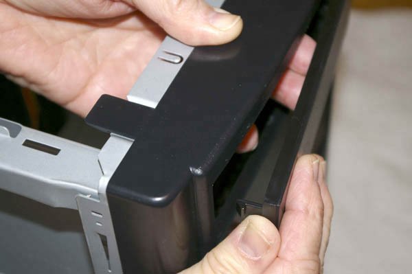 Unlike some cases, the Antec SLK1650B self-aligns the optical drive both vertically and horizontally. To mount the drive in the case, feed the loose end of the ATA cable through the drive bay from the front, and feed the cable down into the case. Align the drive with the mounting rails inside the bay, and slide the drive into the case, as shown in Figure 8-57. Seat the front of the drive bezel flush with the case bezel, and install four screwsleft and right, front and backto secure the drive. Figure 8-57. Slide the optical drive into the bay and set it flush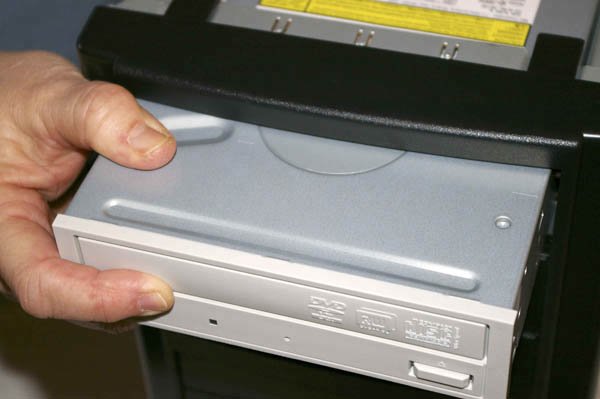
We want to connect the NEC ND-3550A optical drive as the master device on the primary ATA channel. In the past, we left the primary ATA channel unused in systems with S-ATA hard drives, because Windows sometimes became confused if the master device on the primary ATA channel was an optical drive. With recent motherboards, that problem is much less likely, so we now connect the optical drive to the primary ATA channel. The blue primary ATA interface and the black secondary ATA interface are located near the right-front edge of the motherboard near the DIMM slots. Locate pin 1 on the primary ATA interface, align the ATA cable with its red stripe toward pin 1 on the interface, and press the connector into place, as shown in Figure 8-58. Figure 8-58. Connect the optical drive ATA cable to the primary ATA interface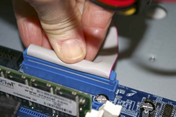 The final step in installing the optical driveone we forget more often than we shouldis to connect power to the drive. Choose one of the power cables coming from the power supply and press the Molex connector onto the drive power connector, as shown in Figure 8-59. It may require significant pressure to get the power connector to seat, so use care to avoid hurting your fingers if the connector seats suddenly. The Molex power connector is keyed, so verify that it is oriented properly before you apply pressure to seat the power cable. Figure 8-59. Connect the power cable to the optical drive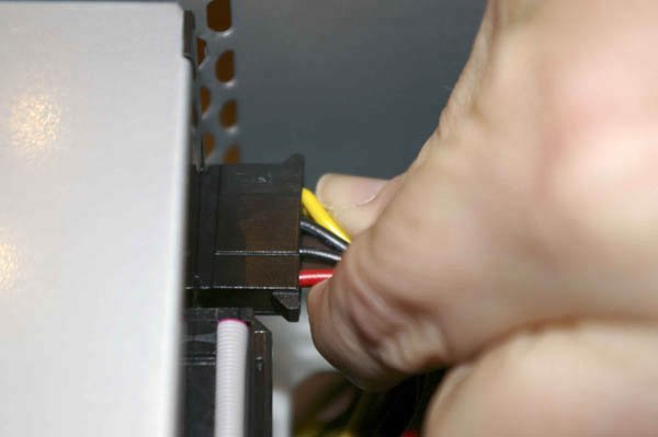
8.4.6. Connecting the ATX Power ConnectorsThe next step in assembling the system is to connect the two ATX power connectors from the power supply to the motherboard. The main ATX power connector supplies most of the power required by the motherboard. The ATX12V power connector provides supplemental (but required) power.
Broadly speaking, there are two types of main ATX power connector. Until recently, most ATX motherboards used the original 20-pin main ATX power connector. The higher current requirements of modern processors led Intel to revise the ATX standard to use a 24-pin main ATX power connector, with the extra four pins carrying additional current at standard voltages. The 24-pin connector is a superset of the older 20-pin connector. The first 20 pins on a 24-pin connector use the same voltages and have the same keying as the 20 pins of the original connector. The extra four pins were simply added onto the end of the old connector. This similarity in layout confers a surprising degree of compatibility between 20-pin power supplies and 24-pin motherboards and vice versa. Current (ATX12V 2.01 and higher) power supplies use the 24-pin connector, as do many (but not all) current motherboards. Most 24-pin motherboards can use a 20-pin power supply if you supplement that power by plugging a standard Molex (hard drive) power connector into a socket on the motherboard. Conversely, most 24-pin power supplies can be used with a 20-pin motherboard by using one of the following workarounds:
Figure 8-60. Connect the Main ATX Power Connector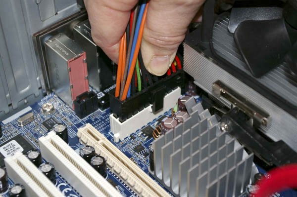 The main ATX power connector is located between the northbridge heatsink and the rear I/O panel. The main ATX power connector is keyed, so verify that it is aligned properly before you attempt to seat it. Once everything is aligned, press down firmly until the connector seats. Figure 8-60 shows the connector in the process of being inserted, just before the black plastic latch on the cable connector snaps into place on the white socket body. It may take significant pressure to seat the connector. Make sure the plug mates completely with the socket, and that the latch snaps into place. A partially seated main ATX power connector may cause subtle problems that are very difficult to troubleshoot. Early Pentium 4 systems required more power to the motherboard than the standard 20-pin ATX main power connector supplied. As a stopgap measure, before they extended the ATX specification to use a 24-pin connector, Intel developed a supplementary connector, called the ATX12V connector. This 4-pin connector routes additional +12V current directly to the VRM (voltage regulator module) that powers the processor. Nowadays, most motherboardsincluding 24-pin models for both Intel and AMD processorsrequire the additional current provided by the ATX12V connector. If you forget to connect the ATX12V cable, the system simply won't boot. On most motherboards, including the ASRock K8NF4G-SATA2, the ATX12V connector is located near the processor socket. Unfortunately, the ASRock motherboard places this connector in a very inaccessible location, at the rear edge of the motherboard near the power supply, leaving almost no room to work. We had a difficult time connecting the ATX12V cable, let alone shooting an image of it. Barbara was finally able to get the connector oriented properly and seat it with one finger, as shown in Figure 8-61. When you seat this connector, make sure the locking tab snaps into place. Figure 8-61. Connect the ATX12V power connector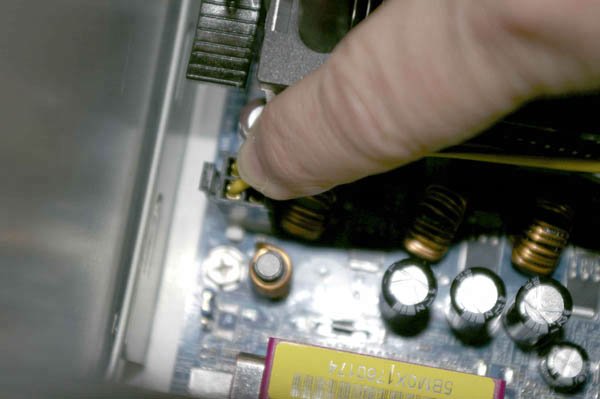 8.4.7. Final Assembly StepsCongratulations! You're almost finished building the system. Only a few final steps remain to be done, and those won't take long.
Figure 8-62. Connect power to the rear case fan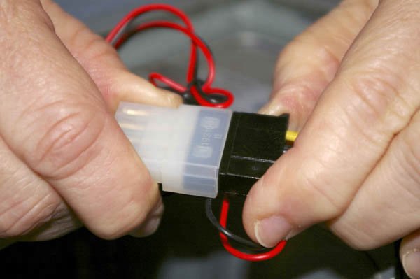 After you've completed these steps, take a few minutes to double-check everything. Verify that all cables are connected properly, that all drives are secured, and that there's nothing loose inside the case. Check one last time to verify the power supply is set for the correct input voltage. It's a good idea to pick up the system and tilt it gently from side to side to make sure there are no loose screws or other items that could cause a short. Use the following checklist:
Now it's time for the smoke test. Leave the cover off for now. Connect the power cable to the wall receptacle and then to the system unit. Unlike many power supplies, the Antec SmartPower 2.0 has a separate rocker switch on the back that controls power to the power supply. By default, it's in the "0" or off position, which means the power supply is not receiving power from the wall receptacle. Move that switch to the "1" or on position. Press the main power button on the front of the case, and the system should start up. Check to make sure that the power supply fan, CPU fan, and case fan are spinning. (Remember that the case fan spins only when needed, so it may not be spinning when you first power up the system.) You should also hear the hard drive spin up and the happy beep that tells you the system is starting normally. At that point, everything should be working properly. |
EAN: 2147483647
Pages: 84