| Previous | Table of Contents | Next |
Case Study: Dynamic IP Routing (OSPF) Using IP Unnumbered Point-To-Point Subinterfaces The sample configuration in Figure 4-20 routes TCP/IP over a partially-meshed Frame Relay network by using point-to-point subinterfaces. 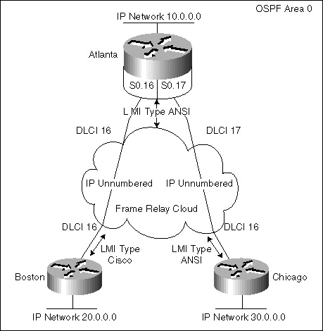
Figure 4-20 Hub-And-Spoke Frame Relay.
IP routes are dynamically resolved by using Open Shortest Path First (OSPF) as the routing protocol. Special care is needed when configuring OSPF over partially-meshed Frame Relay. OSPF requires direct connections to each of its neighbors in order to elect a Designated Router (DR) and form adjacencies with neighboring OSPF routers. However, on a partially-meshed Frame Relay network, the physical topology does not provide the direct access that OSPF requires. The solution to the adjacency problem is to use subinterfaces. In general, it is good practice to use subinterfaces for partially-meshed Frame Relay networks. A Frame Relay network designed by using subinterfaces scales much easier to future expansion. New sites and other protocols (e.g. AppleTalk and IPX) can be added much easier in the future if subinterfaces are used. Moreover, subinterfacing is the preferred method of implementing an OSPF network over Frame Relay. Subinterfaces can be used to split a single, physical interface into separate, virtual point-to-point interfaces. Each subinterface is now treated as its own point-to-point network segment and will require its own IP subnet. Fortunately, IP unnumbered can be used to alleviate the burden of designing the additional subnets as illustrated in the diagram above. With the Frame Relay network broken out into subinterfaces, OSPF will now consider the cloud as a set of point-to-point links rather than one multi-access network. The point-to-point connections will allow the routers to form OSPF adjacencies without DR election. The central router (Atlanta) configuration for the network setup in Figure 4-20 is as follows: version 11.2 <*> service udp-small-servers <*> service tcp-small-servers <*> ! hostname Atlanta ! enable secret cisco ! ip subnet-zero no ip domain-lookup ! interface Ethernet0 ip address 10.1.1.1 255.0.0.0 ! interface Serial0 no ip address <*> encapsulation frame-relay frame-relay lmi-type ansi ! interface Serial0.16 point-to-point description Frame Relay to Boston ip unnumbered Ethernet0 frame-relay interface-dlci 16 broadcast ! interface Serial0.17 point-to-point description Frame Relay to Chicago ip unnumbered Ethernet0 frame-relay interface-dlci 17 broadcast ! router ospf 1 network 10.0.0.0 0.255.255.255 area 0 ! ip http server ip classless ! line con 0 password console login line aux 0 <*> line vty 0 4 password telnet login <*> ! end <*> The remote router (Boston) configuration for the network setup in Figure 4-20 is as follows: version 11.2 <*> service udp-small-servers <*> service tcp-small-servers <*> ! hostname Boston ! enable secret cisco ! ip subnet-zero no ip domain-lookup ! interface Ethernet0 ip address 20.1.1.1 255.0.0.0 ! interface Serial0 no ip address <*> encapsulation frame-relay ! interface Serial0.16 point-to-point description Frame Relay to Atlanta ip unnumbered Ethernet0 frame-relay interface-dlci 16 broadcast ! router ospf 2 network 20.0.0.0 0.255.255.255 area 0 ! ip http server ip classless ! line con 0 password console login line aux 0 <*> line vty 0 4 password telnet login <*> ! end <*> The remote router (Chicago) configuration for the network setup in Figure 4-20 is as follows: version 11.2 <*> service udp-small-servers <*> service tcp-small-servers <*> ! hostname Chicago ! enable secret cisco ! ip subnet-zero no ip domain-lookup ! interface Ethernet0 ip address 30.1.1.1 255.0.0.0 ! interface Serial0 no ip address <*> encapsulation frame-relay frame-relay lmi-type ansi ! interface Serial0.16 point-to-point description Frame Relay to Atlanta ip unnumbered Ethernet0 frame-relay interface-dlci 16 broadcast ! router ospf 3 network 30.0.0.0 0.255.255.255 area 0 ! ip http server ip classless ! line con 0 password console login line aux 0 <*> line vty 0 4 password telnet login <*> ! end <*> Frequently Asked Questions - Q—What type of “bogus” IP address should I use on my router’s loopback interface?
- A—There are several techniques that would work just fine. Consider taking the IP address from the serial interface and transposing the first and last octets. For example, a serial address of 156.245.75.23 would become a loopback address of 23.245.75.156. Any combination of swapping octets around would work or you can make up a scheme that reflects the logic of your network.
- Q—How do I configure a loopback interface on my Cisco router?
- A—Enter the router’s enable mode and then go into global configuration. Determine what number loopback address you want to access and type that into the router, then assign it an IP address and mask. Exit out of configuration mode and do a show interface on that loopback interface and it should be there for you. Examples to do this are provided in Chapter 7.
- Q—How do I decide which router I want to be the Designated Router and Backup Designated Router?
- A—Cisco routers by default do not have the ip OSPF priority ## command turned on. This means that OSPF will default to using the highest IP address on the router as the OSPF router ID. In order for the DR election process to be configured according to your needs, you must do the following:
- 1. Assign the router you desire to be the DR a high priority number by using the command: ip OSPF priority 10, for example.
- 2. Then, using the same command for the BDR, just use a smaller number in the command.
No other router needs to be configured with the OSPF priority command. - Q—What is the multicast address for all OSPF routers?
- A—224.0.0.5
- Q—What is the multicast address for all Designated Routers?
- A—224.0.0.6
- Q—What is an area?
- A—An area is a collection of networks together with routers having interfaces to any of the included networks.
- Q—What technique should I use to number areas? The RFC says to number them like IP addresses.
- A—It is not required nor necessary to number your areas like IP addresses; either way, OSPF will operate just fine. You can use the normal decimal number technique (1, 2, 3, 4, for example) or the method that follows an IP address format. In my opinion, there is an added benefit of being able to make your areas very logical in their naming if you follow the IP address technique.
- Q—What is a stub area?
- A—A stub area is an area in which you don’t allow advertisements of external routes.
- Q—When you define an area to be a stub area by the command area xx stub in every router in the stub area, do you need the area xx default- cost yy command in every router too?
- A—No, area-default-cost yy is only required in area border routers.
- Q—If your network has no externals, is there any benefit to using stub areas?
- A—No, you don’t need the stub area command in the router if your network has no externals.
- Q—When OSPF is configured, does area 0 have to be there?
- A—There is no need to have area 0 if you have only one area in your network. You can use any number as the area ID. You only need area 0 to connect multiple areas if you have more than one area. But, when the Autonomous System is divided into areas, there has to be an area 0 which is the backbone area. The backbone must be contiguous. If the backbone is partitioned, then parts of the Autonomous System will become unreachable. Virtual links can be configured to repair the partition.
- Q—Could you configure an Autonomous System that contained one class B network and used multiple areas with backbone area 0?
- A—Yes.
- Q—Can you use an area ID based on IP addresses?
- A—Yes, Cisco’s implementation takes area ID both in IP address format and decimal number.
- Q—There is a command to set the link-state Retransmit Interval. What is this?
- A—The command ip ospf retransmit <interval> will do this. Each newly received link-state advertisement must be acknowledged. This is done by sending LSA packets. LSAs are retransmitted until they are acknowledged. Link-state Retransmit Interval defines the time between retransmissions. The actual operation of this command is shown in Chapter 6.
- Q—What is a virtual link? When and how is it used?
- A—The backbone area must be contiguous; otherwise some areas of the Autonomous System will become unreachable. Virtual links establish connectivity to the backbone. The two end points of the virtual link are area border routers that both have virtual link configured. Whenever there is an area that does not have a connection to the backbone, the virtual link provides that connectivity. OSPF treats two routers joined by a virtual link as if they were connected by an unnumbered point-to-point network. Virtual links cannot be configured on unnumbered links or through stub areas.
- Q—A great deal of literature suggests that OSPF is a complete solution to the problems of discontiguous addressing in IP nets. However, many people were under the impression that only the static option of the virtual link in OSPF allowed discontiguous nets regardless of the mask propagation properties of OSPF. Is this an accurate statement?
- A—No. Virtual links in OSPF maintain connectivity to the backbone from non-backbone areas, but they are unnecessary for discontiguous addressing. OSPF provides support for discontiguous networks, because every area has a collection of networks and OSPF attaches a mask to each advertisement. However, it is not the panacea for poor network design.
- Q—Is there a limitation on the number of routers in an area?
- A—No, but this all depends on your network, available memory, processing, and so forth. In general, in order for OSPF to scale well, you should have less than 40 routers in an area. Though the factors regarding OSPF’s operation can really make this figure vary, so go slowly.
- Q—All advertisements are sent by using multicast addressing. Are the multicast IP addresses mapped to MAC-level multicast addresses?
- A—Except for Token Ring, the multicast IP addresses are mapped to MAC-level multicast addresses. Cisco maps Token Ring to MAC-level broadcast and functional addresses.
- Q—What is the OSPF MAC Address for multicasting?
- A—01-00-5E-00-00-00
- Q—Does Cisco support the OSPF MIB definitions defined in RFC 1253?
- A—Release 11.0 supports the OSPF MIB as read only and with no trap.
- Q—Does Cisco’s software comply with RFC 1364, “BGP OSPF Interaction?”
- A—Yes.
- Q—Do you have to manually set up adjacencies for routers on the SMDS cloud with the OSPF neighbor subcommand?
- A—In Cisco IOS 9.1, you need the OSPF neighbor command to make OSPF work on SMDS. As of 10.0, you need the ip ospf network broadcast command on the designated router.
- Q—Why must the neighbor command be used when running OSPF over NBMA (Frame Relay, X.25, etc.)?
- A—You need the neighbor command to make OSPF work on NBMA in Cisco IOS 9.1. As of 10.0, at the OSPF level, an NBMA network can be configured as a broadcast network, and OSPF would treat NBMA as a broadcast network only. You would need X.25 maps with BROADCAST keyword to make it work.
- Q—Can I assume that when routes are redistributed between OSPF processes, all SPF metrics are preserved and the default metric value is not used?
- A—Metrics are not preserved. The redistribution between them is like redistribution between any two IP routing processes.
- Q—What do the states DR/OTHER, DR, and BDR mean in sh IP OSPF int output?
- A—DR means Designated Router, BDR means Backup Designated Router, and DR/OTHER means a router that is neither the DR nor the BDR. DR will generated a Network LSA representing that network, listing all the routers on that network.
I have the following setup: 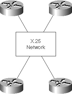
Figure 4-19d X.25 network setup.
- Q—R1 through R4 are running OSPF, and each router is declared as neighbor in the other three. I want to connect R5, a fifth router, to that network. Can I declare R5 as neighbor of the Designated Router only, and still get the whole routing table?
- A—You need to list all the routers only in the routers eligible for DR/BDR. If you list R5 only in the present DR, you might have some problems when that DR goes down and routers are trying to become DR/BDR. If you think a router should not be allowed to become DR or BDR (its priority is set to 0), there is no need to list any routers in that router. As of Cisco IOS 10.0, Cisco routers allow these nonbroadcast networks to be configured as broadcast so as to avoid all this neighbor configuration.
- Q—How does Cisco accommodate OSPF routing on partial-mesh Frame Relay networks? What about other routing protocols, like RIP and IGRP?
- A—You can configure OSPF to understand whether or not it should attempt to use multicast facilities on a multi-access interface. Also, if multicast is available, OSPF will use it for its normal multicasts.
Cisco IOS 10.0 includes a feature called “subinterfaces.” This feature can be used with Frame Relay and similar interfaces to tie a set of VCs together to form a virtual interface, which acts as a single IP subnet. All systems within the subnet are expected to be fully meshed. This feature is routing protocol independent. As of 10.3 and 11.0, point-to-multipoint is also available.
RIP and IGRP have had other enhancements to deal with this same situation since Cisco IOS 8.3(3). - Q—The ip ospf network subcommand associates router interfaces with OSPF areas, and it requires an address-wildmask pair. Which address-wildmask pair should be used for assigning an unnumbered interface to an area?
- A—Use the address-wildmask pair of the interface to which the unnumbered interface is pointing.
- Q—Does Cisco support RIP to OSPF redistribution over X.25 IP unnumbered?
- A—Yes.
- Q—In Cisco IOS 9.1, is the neighbor command required when running OSPF over X.25 networks?
- A—You need the neighbor command to make OSPF work on X.25 in Cisco IOS 9.1. In 9.21 and later, at OSPF level, an X.25 network can be configured to be a broadcast network, and OSPF treats X.25 as a broadcast network only. X.25 maps with the “broadcast” keyword are be needed to make it work.
- Q—Does Cisco support RIP to OSPF redistribution over X.25 IP unnumbered?
- A—Yes.
- Q—Does Cisco support RIP to OSPF redistribution over X.25 IP unnumbered?
- A—Yes.
- Q—In Cisco IOS 9.1, is the neighbor command required when running OSPF over X.25 networks?
- A—You need the neighbor command to make OSPF work on X.25 in Cisco IOS 9.1. In 9.21 and later, at OSPF level, an X.25 network can be configured to be a broadcast network, and OSPF treats X.25 as a broadcast network only. X.25 maps with the “broadcast” keyword are be needed to make it work.
- Q—Does Cisco support RIP to OSPF redistribution over X.25 IP unnumbered?
- A—Yes.
| Previous | Table of Contents | Next |
|