Introduction to OSPF
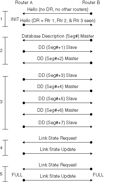
Link-State Database Synchronization Figure 4-10 illustrates the initial synchronization of the link-state database, which occurs in five steps as detailed in the numbered sequence following the figure.
The states for link-state database synchronization as illustrated in Figure 4-10 are as follows:
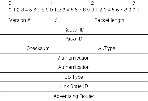
During the five steps of link-state database synchronization, normal LSAs are not sent. Instead, the routers exchange packets known as Database Description (DD) packets, which are type 2 packets that are used when an adjacency is being initialized and the two routers in question are exchanging and synchronizing their link-state databases. These DD packets contain the contents of the link-state database. Figure 4-12 shows the fields and information contained within each DD packet.
Of course, multiple packets might be needed to complete the synchronization and in that case a poll-response procedure is used with one router becoming the master and the other the slave. LSA Packet Types Unlike distance vector protocols (RIP or IGRP), OSPF does not actually send its routing table to other routers. Instead, routing tables are derived from the LSA database. Table 4-1 lists and describes the six different types of LSA packets that can be generated by the source router and entered into the destination router’s LSA database.
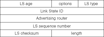
Although there are several different types of LSAs and each has a unique packet structure to reflect the information it contains, they all share a common header as shown in Figure 4-13.
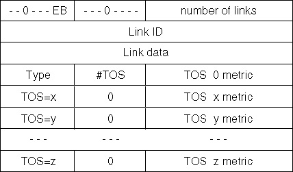
The sections that follow provide general descriptions of the six different LSA packet types. Type 1: Router LSAs Router LSAs are generated by each router for each area to which it belongs. These packets describe the states of the router’s links to the area and are only flooded within a particular area. The link-state ID is the originating router’s ID. Figure 4-14 shows the layout of each Router LSA packet.
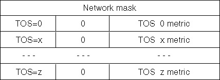
Type 2: Network LSAs Network LSAs are generated by Designated Routers (DR) and describe the set of routers attached to a particular network. They are flooded in the area that contains the network. The link-state ID is the IP interface address of the DR. Figure 4-15 shows the layout of each Network LSA packet.
Type 3: Summary LSAs for ABRs Summary LSAs are generated by Area Border Routers (ABRs) and describe inter-area routes to various networks. They can also be used for aggregating routes. The link-state ID is the destination network number. Figure 4-16 shows the layout of each Summary LSA packet.
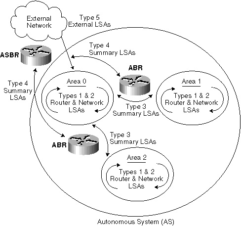
Type 4: Summary LSAs for ASBRs Summary LSAs describe links to Autonomous System Border Routers (ASBRs) and are also generated by Area Border Routers (ABRs). The link-state ID is the router ID of the described ASBR. Figure 4-16 (shown previously) illustrates the layout of each packet. Type 5: Autonomous System External LSAs Type 5 LSAs are generated by the Autonomous System Border Routers (ASBRs). They describe routes to destinations external to the Autonomous System. They will be flooded everywhere with the exception of stub areas. The link-state ID is the external network number. Type 7: Not-So-Stubby Area (NSSA) Type 7 LSAs are generated by Area Border Routers (ABRs). They describe routes within the NSSA. They can be summarized and converted into Type 5 LSAs by the ABRs. After they are converted to Type 5 LSAs, they will be distributed to areas that can support Type 5 LSAs. Refer to RFC 1587 for further details on how this conversion is done. Link-State Advertisement Operation Example Now that all six LSAs have been discussed and you understand how they operate within the OSPF functional environment, refer to Figure 4-17 for a visual representation for the operation and interaction between the various types of LSAs within an OSPF network.
| ||||||||||||||||||||||

EAN: 2147483647
Pages: 200