Introduction to OSPF
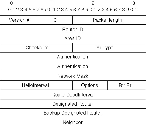
Hello Protocol Packet Format The OSPF Hello protocol packets are formatted in only one way. All OSPF packets start with a standardized 24-byte header which contains information that determines whether processing will take place on the rest of the packet. The packets contain the fields shown in Figure 4-6, always in the same order. All the fields in this format are 32 bits, except for the following fields: HelloInterval, which is 16 bits; Options, which is 8 bits; and Priority, which is 8 bits.
The following list describes what each of the packet fields represents.
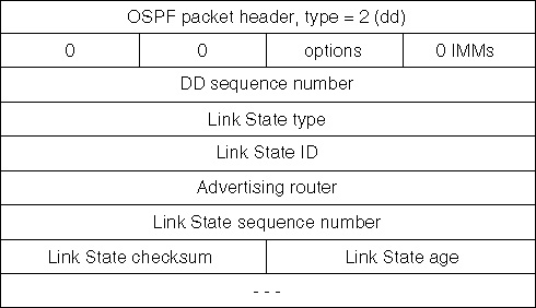
The Exchange Protocol When two OSPF routers have established bi-directional communication, or two-way communication, they will synchronize their routing (link-state) databases. For point-to-point links, the two routers will communicate this information directly between themselves. On network links (that is, multiaccess network, either broadcast or nonbroadcast) this synchronization will take place between the new OSPF router and the DR. The Exchange protocol is first used to synchronize the routing (link-state) databases. After synchronization, any changes in the router’s links will use the Flooding protocol to update all the OSPF routers. An interesting note about the operation of this protocol is that it is asymmetric. The first step in the exchange process is to determine who is the master and who is the slave. After agreeing on these roles, the two routers will begin to exchange the description of their respective link-state databases. This information is passed between the two routers via the Exchange protocol packet layout as shown in Figure 4-7.
As they receive and process these database description packets, the routers will make a separate list that contains the records they will need to exchange later. When the comparisons are complete, the routers will then exchange the necessary updates that were put into the list so that their databases can be kept up to date. The Flooding Protocol OSPF’s Flooding subprotocol is responsible for distributing and synchronizing the link-state database whenever a change occurs to a link. When a link changes state (from up to down), the router that experienced the change will issue a Flooding packet which contains the state change. This update is flooded out to all of the routers’ interfaces. In an attempt to ensure that the flooded packet has been received by all of its neighbors, the router will continue to retransmit the update until it receives an acknowledgement from its neighbors.
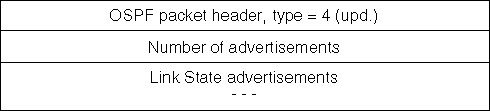
There are two ways in which OSPF can acknowledge an update. The first is when the destination router sends an acknowledgement directly to the source router. In this case, there is no DR in use by OSPF if this is occurring. The second way is when a DR is in use and it receives the update; it will immediately retransmit this update to all other routers. Therefore, when the sending router hears this retransmission, it is considered an acknowledgement, and no further action will be taken. Figure 4-8 shows the field names and layout of the packet for the Flooding subprotocol.
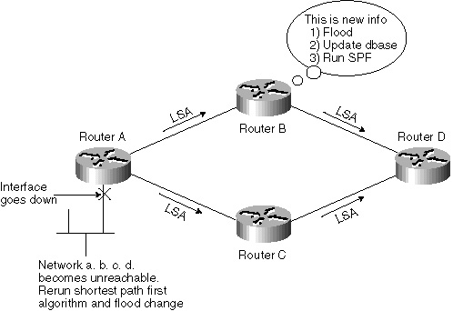
Link-State Advertisement (LSA)A link is any type of connection between OSPF routers, like a serial interface. The state is the condition of the link, whether it is up or down. An advertisement is the method OSPF uses to provide information to other OSPF routers. You could say that link-state advertisements are packets that OSPF uses to advertise changes in the condition of a specific link to other OSPF routers. There are six different and distinct link-state packet formats in use by OSPF, each of which is generated for a different purpose that helps keep the OSPF network routing table intact and accurate. Although there are six different packet types, these are shown later in this section. When a router receives an LSA, it checks its link-state database. If the LSA is new, the router floods the LSA out to its neighbors. After the new LSA is added to the LSA database, the router will rerun the SPF algorithm. This recalculation by the SPF algorithm is absolutely essential to preserving accurate routing tables. The SPF algorithm is responsible for calculating the routing table and any LSA change might also cause a change in the routing table. Figure 4-9 demonstrates this transaction where Router A loses a link and recalculates the shortest path first algorithm and then floods the LSA change out to the remaining interfaces. This new LSA is then analyzed by routers B and C, which recalculate and continue to flood the LSA out the other interfaces to Router D.
|
EAN: 2147483647
Pages: 200