Networking Routing Fundamentals
Consider an example of a router that is initially configured with two networks to which it is directly connected. The router will have only these two networks in its routing tables. However, because there are other networks beyond the initial two, they are not entered into the routing table because they are not directly connected to the router. Then how are these other networks recognized by the router? Simply put, there are three ways in which this can be accomplished:
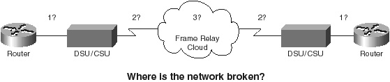
Overall, dynamic routing is the most commonly used method of routing. Associated with this type of routing are several terms and characteristics that assist in defining how it is to operate. It is fundamental to dynamic routing that the routing table consistently reflects accurate and up-to-date information concerning the network topology. The amount of time it takes for changes to be reflected in every network router’s routing table is known as convergence. Convergence is defined as the speed and capability of a group of internetworking devices (such as routers) running a routing protocol to agree on the new topology of an internetwork after a change occurs in the existing topology. Having a routing protocol with a fast convergence time is very desirable because disruption of routing can occur during the time a router spends calculating the new optimal path. Chapter SummaryThis chapter discussed routing fundamentals within a network, whether to the Internet or an intranet. All networks require a certain amount of “common” information with which to operate. Chapter 1 discussed many of the more common physical topologies and how the OSI model was used as a template for network communications. This chapter built on that overlay through the discussion of IP addressing, network protocols, and routing components. These three topics have built a foundation of basic networking and routing fundamentals. The section “IP Addressing” provided an overview of how addresses are classified. You were also familiarized with several commonly used techniques to help better manage your IP addresses: subnet masking, variable length subnet masking (VLSM), and classless interdomain routing (CIDR). The section “Routing Components” defined and listed the use, function, and purpose of the actual equipment needed to make a network operate. You also learned about some of the more commonly used terms within this environment. The final section of this chapter, “Network Protocols,” emphasized the difference between routed and routing protocols. This section also briefly discussed some of the more important characteristics and background of the TCP/IP protocol stack. With this information and understanding, Chapter 3 will move on to cover how to understand and select a network protocol, with an emphasis on OSPF. Case Study: Where Is the Network Broken?You can acquire a variety of useful information when designing a good network. When implementing or troubleshooting, there are many factors that can affect the network. This case study will briefly discuss some of the techniques that you can use to ensure that during the many phases of network development, you have the tools necessary to troubleshoot any problems in a network, such as that illustrated in Figure 2-11.
After a Frame Relay line has been properly provisioned by the provider, the installation of a Frame Relay network using Cisco routers is usually a trouble-free task involving minimal configuration. However, if problems arise in a Frame Relay network, proven techniques can be applied to help isolate and solve them. Troubleshooting a Frame Relay network problem can be broken down into four easy steps:
Cisco routers offer extensive diagnostic tools to assist in the previous tasks. However, most Frame Relay problems can be diagnosed by using the following simple commands:
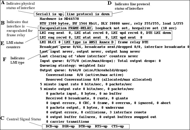
Verifying the Physical Connection Between the DSU/CSU and the RouterAbove all else, a good physical connection must exist between the router and the local DSU/CSU. You can use the show interface command to determine the status of the physical connection. Figure 2-12 is a sample output of a show interface serial1 command.
Referring to Figure 2-12, the field marked with an “A” indicates the physical status of the interface. An interface can be in one of three possible states: up, down, or administratively down. The following sections outline the possible states and offer some suggested actions to correct physical connection problems. Interface State: Serial x Is Up If serial x is up, this is an indication that the interface has a good connection to the DSU/CSU. Proceed to Step 2 and verify that the router and Frame Relay provider are properly exchanging LMI. Interface State: Serial x Is Administratively Down If serial x is administratively down, this is an indication that the interface is in shutdown mode. The following commands are used to take an interface out of shutdown:
|
EAN: 2147483647
Pages: 200