8.1 Routing Protocol Primer
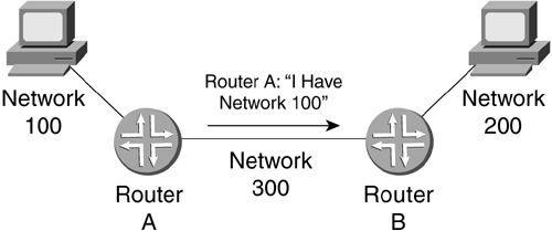
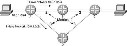
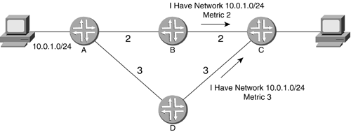
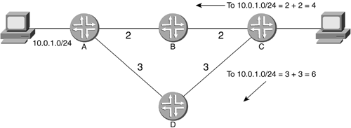
| Originally, all of the connections between routers were manually entered static routes. Each router had to have an entry for every network, along with explicit paths by which to reach those other networks. Every time one network was added, every router had to be manually configured with an entry for that network. In addition, if a failure occurred, these entries would have to be changed, again manually, to route around the break. This could cause quite an administrative headache to monitor as a network grew. Dynamic routing protocols solved this administrative nightmare by enabling routers to tell each other of the networks to which they were connected. They also allowed routers to decide on a path through a network based on the status of the networks in between. This relieved the administrator from having to reconfigure the routers every time something changed. Suddenly, the prospect of drastic network growth and redundancy was not so frightening. Additions, deletions, modifications, and failures of networks no longer required the intervention of administrators at every network hop. Dynamic routing protocols can be classified into two groups by function: interior and exterior routing. IGPs, or Interior Gateway Protocols, are usually used within a network under a single administrative entity. This administrative entity could be a single company or a single ISP. A very large company or ISP might have to break a network into several administrative entities to maintain manageability. A network under a single administration is called an autonomous system, or AS. EGPs, or Exterior Gateway Protocols, are the protocols that are used to connect different ASs and will be discussed in Chapter 9. A router's main function is to connect networks together for communication at Layer 3, the network layer of the OSI model. A Juniper Networks router can be directly connected to hundreds of networks. One router telling another router of its connected networks is known as advertising. Advertisements need to be standardized so that routers from different manufacturers can all understand each other. In Figure 8-1, routers A and B are connected through Network 300. Router A has a direct connection to Network 100, and router B has a direct connection to Network 200. Router A sends an advertisement to router B advertising Network 100. When a device on Network 200 sends data destined for Network 100, router B understands that it should forward that data out of the interface connected to router A (via Network 300) for forwarding. Router B knows router A as the next -hop for Network 100 because it is the next router in the route towards Network 100, the destination. Figure 8-1. Route Advertisement As a router receives advertisements from neighboring routers, it will store them in a routing information base (RIB), which will allow the router to make the best decision as to which direction or route it will use to forward packets to a particular destination network. With some protocols, routers will blindly send out an advertisement containing its entire set of known networks. With other protocols, routers can form route exchange relationships called adjacencies. This communication between adjacent routers allows the routers to keep track of the data they have sent to each other so the whole set of advertisements does not have to be sent out every time. Routers initially tell each other of their own directly connected networks. Routers will then pass on the information they have learned from close neighbors to other close neighbors. This creates a growing chain of knowledge for routers to use to forward to destinations many routers away. One issue that can complicate things is the availability of more than one way to get to a particular destination network. A decision has to be made as to which path the router will prefer. 8.1.1 Router MetricsWhen a router receives information about different routes to a destination network, it has to make a decision as to which route is best. This is known as a routing decision. Different routing protocols will favor different elements of route information over others. These elements of information, such as how far away a router is (how many routers away, also known as the hop count ) or which are the fastest links to a destination, are collectively known as routing metrics. Metrics are informational units that can be measured and compared. If the distance to a network is a determining factor in the routing decision, then the hop count is a metric. Metrics can be different things for different protocols. RIP might use just the hop count. OSPF uses hop count and bandwidth availability to create a metric for decision-making purposes. Metrics can be described as additive in nature. These additive metrics are known as cost functions. The farther an advertisement travels from the originating routers, the larger the metric grows. The metric to the destination network in the advertisement is increased as it crosses each hop. In Figure 8-2, notice there are different metrics associated with the networks connecting the routers. The metric between routers A and B is 2, while the metric between routers A and D is 3. Router A advertises network 10.0.1.0/24 to routers B and D. When routers B and D receive the advertisement, they forward their knowledge to router C with the associated metric for that link added, as shown in Figure 8-3. Figure 8-2. Sending Advertisements to Other Routers Figure 8-3. Forwarding Advertisements Router C receives the two advertisements and computes which path to 10.0.1.0/24 has the lower metric, as Figure 8-4 shows. When the workstation connected to router C sends data to router C intended for the device on the 10.0.1.0/24 network, router C has two different routes to choose from. From the previous advertisements, router C knows that 10.0.1.0/24 has a metric of 4 when going through the interface connected to router B. The path to the same network has a metric of 6 when going through router D. Router C will make a decision to forward the data out of the interface connected to router B for 10.0.1.0/24 . The route through D can be used as a backup, in case the route through router B suffers an outage . Figure 8-4. Evaluating Metrics Metrics may also be manipulated administratively. This allows an administrator to change metrics, thereby causing routers to change their forwarding behavior as the administrator desires. An administrator for the example shown in Figure 8-4 could have manually changed the metric of the connection between router B and router A to 5. When the advertisement reached router C, the total metric would have added up to 7, forcing router C to choose router D for traffic forwarded to network 10.0.1.0/24 . Approved standards can describe the proper functioning of routers, routing protocols, connected networks, links, and the way all of these are advertised to other devices. These actions comprise some of the standards for routing protocols. This is how a router learns about the network. 8.1.2 Distance Vector Versus Link StateRouting protocols can be also be classified into two different types that have to do with how the information they receive is stored and how that information is sent to their neighbors. These two protocol types are distance vector and link state. Distant vector protocols are blind to nondirectly connected networks and routers. They only keep track of how many hops away a destination network is and out of which interface the router needs to send the packet to get the packet to the next-hop. They have no sense of place in a network. Every router passes on every route advertisement it receives. Link state protocols, on the other hand, keep track of all the routers and routes in the network by keeping a database on the topology of the network. When a router's interface is configured, the network on which the interface resides is considered directly connected. Routers send their directly connected network information to each other. One router will pass on another router's information without changing it. As this information is passed around, each router can create a topological map of all the routers in the network, the links that connect them, and the state of those links (hence the name link state). Knowing the state of the networks and links allows a router to respond to changes in a network more quickly. The term convergence describes a state when all of the routers have the same correct information on the state of the network after a change. When a change occurs, such as a link failure, the convergence time is the time it takes for the information to reach all of the routers (to the routers farthest from the outage) and for all of the routers to recalculate their new routes. As opposed to a distance vector protocol, which has to send entire routing tables, link state protocols allow for faster convergence by sending only the updated data. If a link fails, routers can notify each other immediately or can wait for a period of time before telling the other routers about the link failure. If a link is having problems and goes up and down many times (which is known as a route flap condition ), immediate notification can drastically increase the traffic on a network, causing a rippling effect of the updates the point of failure. The alternative is to wait a certain amount of time before sending out the news of a link failure. In addition, if a route to a distant network is not updated within a certain period of time, it will be considered to be down. 8.1.3 Juniper Networks Router ConfigurationBasic configuration of routing protocols in JUNOS takes place in the [edit protocols (protocol) command hierarchy of the CLI, where (protocol) represents which protocol you wish to configure. Most of the configuration for the protocols is done in this command hierarchy. An example of a protocol action would be configuring a protocol to run on an interface. Shown here is a CLI example of the protocols that can be configured on a Juniper Networks router. lab@Chicago> configure Entering configuration mode [edit] lab@Chicago# edit protocols [edit protocols] lab@Chicago# set ? Possible completions: + apply-groups Groups from which to inherit configuration data > bgp BGP options > connections Circuit cross-connect configuration > dvmrp DVMRP options > igmp IGMP options > isis IS-IS options > ldp LDP options > mpls Multiprotocol Label Switching options > msdp MSDP options > ospf OSPF configuration > pim PIM options > rip RIP options > router-discovery ICMP router discovery options > rsvp RSVP options > sap Session Advertisement Protocol options > vrrp VRRP options [edit protocols] lab@Chicago# Here you have learned what a routing protocol is. It is a set of communication standards that routers can use to advertise networks. The information carried in these advertisements allows other routers to make an informed decision as to the best route to use when forwarding traffic to a particular destination. Now we will introduce specific routing protocols that can be used on Juniper Networks routers. |
EAN: 2147483647
Pages: 176


