Switching Types
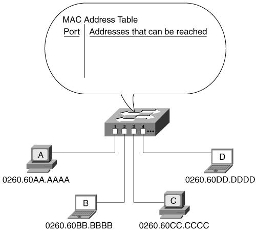
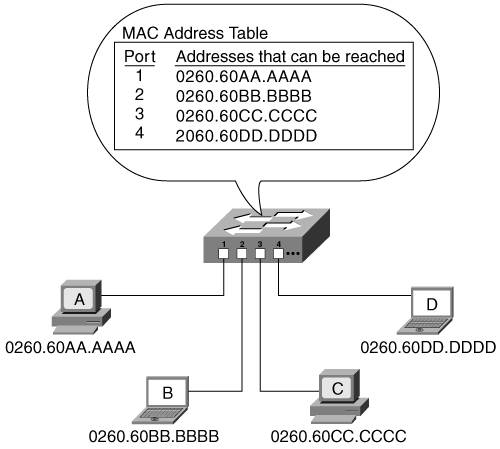
| Switches were initially introduced to provide higher-performance connectivity than hubs, because switches define multiple collision domains. Switches have always been able to process data at a faster rate than routers, because the switching functionality is implemented in hardwarein Application-Specific Integrated Circuits (ASICs)rather than in software, which is how routing has traditionally been implemented. However, switching was initially restricted to the examination of Layer 2 frames. With the advent of more powerful ASICs, switches can now process Layer 3 packets, and even the contents of those packets, at high speeds. The following sections first examine the operation of traditional Layer 2 switching. Layer 3 switchingwhich is really routing in hardwareis then explored. Layer 2 SwitchingKey Point Layer 2 switches segment a network into multiple collision domains and interconnect devices within a workgroup, such as a group of PCs. The heart of a Layer 2 switch is its Media Access Control (MAC) address table, also known as its content-addressable memory (CAM). This table contains a list of the MAC addresses that are reachable through each switch port. (Recall that the physical MAC address uniquely identifies a device on a network. When a network interface card is manufactured, the card is assigned an addresscalled a burned-in address [BIA]which doesn't change when the network card is installed in a device and is moved from one network to another. Typically, this BIA is copied to interface memory and is used as the MAC address of the interface.) The MAC address table can be statically configured, or the switch can learn the MAC addresses dynamically. When a switch is first powered up, its MAC address table is empty, as shown in the example network of Figure 2-1. Figure 2-1. The MAC Address Table Is Initially Empty In this example network, consider what happens when device A sends a frame destined for device D. The switch receives the frame on port 1 (from device A). Recall that a frame includes the MAC address of the source device and the MAC address of the destination device. Because the switch does not yet know where device D is, the switch must flood the frame out of all the other ports; therefore, the switch sends the frame out of ports 2, 3, and 4. This means that devices B, C, and D all receive the frame. Only device D, however, recognizes its MAC address as the destination address in the frame; it is the only device on which the CPU is interrupted to further process the frame. In the meantime, the switch now knows that device A can be reached on port 1 (because the switch received a frame from device A on port 1); the switch therefore puts the MAC address of device A in its MAC address table for port 1. This process is called learningthe switch is learning all the MAC addresses that it can reach. At some point, device D is likely to reply to device A. At that time, the switch receives a frame from device D on port 4; the switch records this information in its MAC address table as part of its learning process. This time, the switch knows where the destination, device A, is; the switch therefore forwards the frame only out of port 1. This process is called filteringthe switch is sending the frames only out of the port through which they need to gowhen the switch knows which port that israther than flooding them out of all the ports. This reduces the traffic on the other ports and reduces the interruptions that the other devices experience. Over time, the switch learns where all the devices are, and the MAC address table is fully populated, as shown in Figure 2-2. Figure 2-2. The Switch Learns Where All the Devices Are and Populates Its MAC Address Table The filtering process also means that multiple simultaneous conversations can occur between different devices. For example, if device A and device B want to communicate, the switch sends their data between ports 1 and 2; no traffic goes on ports 3 or 4. At the same time, devices C and D can communicate on ports 3 and 4 without interfering with the traffic on ports 1 and 2. Thus, the overall throughput of the network has increased dramatically. The MAC address table is kept in the switch's memory and has a finite size (depending on the specific switch used). If many devices are attached to the switch, the switch might not have room for an entry for every one, so the table entries will time out after a period of not being used. For example, the Cisco Catalyst 2950 switch defaults to a 300-second timeout. Thus, the most active devices are always in the table. Note Cisco LAN switches are also known as Catalyst switches. Key Point Broadcast and multicast frames are, by default, flooded to all ports of a Layer 2 switch, other than the incoming port. The same is true for unicast frames that are destined to any device that is not in the MAC address table. MAC addresses can also be statically configured in the MAC address table, and you can specify a maximum number of addresses allowed per port. One advantage of static addresses is that less flooding occurs, both when the switch first comes up and because of not aging out the addresses. However, this also means that if a device is moved, the switch configuration must be changed. A related feature available in some switches is the ability to sticky-learn addressesthe address is dynamically learned, as described earlier, but is then automatically entered as a static command in the switch configuration. Limiting the number of addresses per port to one and statically configuring those addresses can ensure that only specific devices are permitted access to the network; this feature is particularly useful when addresses are sticky-learned. Layer 3 SwitchingKey Point A Layer 3 switch is really a router with some of the functions implemented in hardware to improve performance. In other words, some of the OSI model network layer routing functions are performed in high-performance ASICs rather than in software. In Appendix B and Chapter 3, "IPv4 Routing Design," we describe the following various functions and characteristics of routers:
These tasks can be CPU intensive. Offloading the switching of the packet to hardware can result in a significant increase in performance. A Layer 3 switch performs all the previously mentioned router functions; the differences are in the physical implementation of the device rather than in the functions it performs. Thus, functionally, the terms router and Layer 3 switch are synonymous. Layer 4 switching is an extension of Layer 3 switching that includes examination of the contents of the Layer 3 packet. For example, as described in Appendix B, the protocol number in the IP packet header indicates which transport layer protocol (for example, Transmission Control Protocol [TCP] or User Datagram Protocol [UDP]) is being used, and the port number in the TCP or UDP segment indicates the application being used. Switching based on the protocol and port numbers can ensure, for example, that certain types of traffic get higher priority on the network or take a specific path. Depending on the switch, Layer 3 switching can be implemented in two different ways within Cisco switchesthrough multilayer switching and Cisco Express Forwarding. These terms are described in the section "Multilayer Switching and Cisco Express Forwarding," later in this chapter (after we discuss VLANs, which you must understand before you read that section). |
EAN: 2147483647
Pages: 156