The OSI Seven Layer ModelWhat Is a Layer?
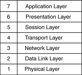
The OSI Seven Layer Model”What Is a Layer?Established in 1947, the International Organization for Standardization (ISO) was formed to bring together the standards bodies from countries around the world. Their definition of the model for Open Systems Interconnection, or OSI, is used to define modes of interconnection between different components in a networking system. This means that the physical method of transport can be designed independently of the protocols and applications running over it. For example, TCP/IP can be run over both Ethernet and FDDI networks, and Novell's IPX and Apple's AppleTalk protocols can both be run over Token Ring networks. These are examples of having independence between the physical network type and the upper layer protocols running across them. Consider also, two TCP/IP-enabled end systems communicating across a multitude of different network types, such as Ethernet, Frame Relay, and ATM. Figure 2-1 shows the OSI Seven Layer Model. Figure 2-1. The OSI Seven Layer Model. When we talk about Layer 2 and Layer 3 networking, it is these layers that we're referring to, and logically the further up the OSI model we move, the greater intelligence we can use in networking decisions. Each layer plays its part in moving data from one device to another across a network infrastructure by providing a standard interface to the surrounding layers. The Application Layer (Layer 7)The top layer in the stack, the Application layer is where the end-user application resides. Think of the Application layer as the browser application or email client for a user surfing the Web or sending email. Many protocols are defined for use at the Application layer, such as HTTP, FTP, SMTP, and Telnet. In content switching terms, Layer 7 refers to the ability to parse information directly generated by the user or application in decision making, such as the URL typed by the user in the Web browser. For example, http://www.foocorp.com is an example of Application layer data. The Presentation Layer (Layer 6)The Presentation layer is used to provide a common way for applications (residing at the Application layer) to translate between data formats or perform encryption and decryption. Mechanisms to convert between text formats such as ASCII and Unicode may be considered part of the Presentation layer, along with compression techniques for image files such as GIF and JPEG. The Session Layer (Layer 5)The Session layer coordinates multiple Presentation layer processes communicating between end devices. The Session layer is used by applications at either end of the communication between end devices to tie together multiple Transport layer sessions and provide synchronization between them. The HTTP protocol can use multiple TCP connections to retrieve objects that make up a single Web page. The Session layer provides application coordination between these separate TCP connections. The Transport Layer (Layer 4)The Transport layer is responsible for providing an identifiable and sometimes reliable transport mechanism between two communicating devices. User or application data, having passed through the Presentation and Session layers, will typically be sequenced and checked before being passed down to the Network layer for addressing. The Transport layer is the first at which we see the concept of packets or datagrams of information that will be transported across the network. TCP, UDP, and ICMP are examples of Layer 4 protocols used to provide a delivery mechanism between end stations . It is also at this layer in the model that applications will be distinguished by information in the Layer 4 headers within the packets. Content switching operates most commonly at this layer by using this information to distinguish between different applications and different users using the same application. The Network Layer (Layer 3)Whereas Layer 4 is concerned with transport of the packets within a communication channel, the Network layer is concerned with the delivery of the packets. This layer defines the addressing structure of the internetwork and how packets should be routed between end systems. The Network layer typically provides information about which Transport layer protocol is being used, as well as local checksums to ensure data integrity. Internet Protocol (IP) and Internet Packet Exchange (IPX) are examples of Network layer protocols. Traditional Internet routers operate at the Network layer by examining Layer 3 addressing information before making a decision on where a packet should be forwarded. Hardware-based Layer 3 switches also use Layer 3 information in forwarding decisions. Layer 3 routers and switches are not concerned whether the packets contain HTTP, FTP, or SMTP data, but simply where the packet is flowing to and from. The Data Link Layer (Layer 2)The Data Link layer also defines a lower level addressing structure to be used between end systems as well as the lower level framing and checksums being used to transmit onto the physical medium. Ethernet, Token Ring, and Frame Relay are all examples of Data Link layer or Layer 2 protocols. Traditional Ethernet switches operate at the Data Link layer and are concerned with forwarding packets based on the Layer 2 addressing scheme. Layer 2 Ethernet switches are not concerned with whether the packet contains IP, IPX, or AppleTalk, but only with where the MAC address of the recipient end system resides. The Physical Layer (Layer 1)As with all computer systems, networking is ultimately about making, moving, and storing 1s and 0s. In networking terms, the Physical layer defines how the user's browser application data is turned into 1s and 0s to be transmitted onto the physical medium. The Physical layer defines the physical medium such as cabling and interface specifications. AUI, 10Base-T, and RJ45 are all examples of Layer 1 specifications. Putting All the Layers TogetherLet's take an example of a Web user visiting the Web site of Foocorp, Inc. Within the browser application, at the Application layer, the user will type in the URL, typically something like http://www.foocorp.com/ . While this is the only input the user will provide the application, there is much more information generated by the browser application itself, including:
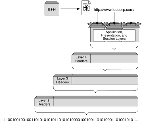
In terms of HTTP-based Web browser traffic, these pieces of information can be thought of as the Application, Presentation, and Session layers of the OSI model. They provide not only the raw data input by the user in the application, but also information needed by the application to ensure successful communication with the end system; in this case, a Web server at Foocorp. HTTP information for the Web user would look something like: Hypertext Transfer Protocol GET / HTTP/1.0\r\n Accept: image/gif, image/x-xbitmap, image/jpeg, image/pjpeg\r\n Accept-Language: en-gb\r\n User-Agent: Mozilla/4.0 (compatible; MSIE 5.01; Windows NT 5.0)\r\n Host: www.foocorp.com\r\n Connection: Keep-Alive\r\n \r\n Once this application information has been generated, it can be packaged and passed on to the next layer for transport. HTTP requires a connection-oriented Transport layer protocol to guarantee the delivery of each packet in the session. Transmission Control Protocol (TCP) is used in HTTP applications to ensure this successful packet delivery. Other applications will make use of different Transport layer protocols. TFTP, for example, uses the User Datagram Protocol (UDP) as its Layer 4 transport because it does not require the guaranteed delivery provided by TCP. Routing updates sent between Layer 3 devices can use OSPF, RIP, or BGP as their Layer 4 transport. At the Transport layer, information about the port numbers, sequence numbers , and checksums are included to provide reliable transport. The Layer 4 headers in our example would look something like: Transmission Control Protocol Source port: 3347 (3347) Destination port: http (80) Sequence number: 52818332 Next sequence number: 52818709 Acknowledgement number: 3364222344 Header length: 20 bytes Flags: 0x0018 (PSH, ACK) 0... .... = Congestion Window Reduced (CWR): Not set .0.. .... = ECN-Echo: Not set ..0. .... = Urgent: Not set ...1 .... = Acknowledgment: Set .... 1... = Push: Set .... .0.. = Reset: Not set .... ..0. = Syn: Not set .... ...0 = Fin: Not set Window size: 17520 Checksum: 0xb043 (correct) Once the Transport layer information has been added to the head of the packet, it is passed to the Network layer for the Layer 3 headers to be appended. The Network layer will include information on the IP addresses of both the client and the end system, and a reference to which Transport layer protocol has been used. The Network layer information is used to ensure the correct delivery path from the client to the end system and the ability for the receiver to identify which Transport layer process the frames should be forwarded to once they arrive . For the Web user example, the Network layer information would look as follows : Internet Protocol Version: 4 Header length: 20 bytes Time to live: 128 Protocol: TCP Header checksum: 0x2df9 (correct) Source: 192.168.254.201 (192.168.254.201) Destination: 216.239.51.101 (216.239.51.101) For transmission across the local, physical network, the frame is then passed to the Data Link layer for the addition of the local physical addresses. In terms of Ethernet, this would be the Ethernet Media Access Control (MAC) address of the user machine and the MAC address of the default gateway router on the Ethernet network. The Layer 2 protocol, such as Ethernet, will also include a reference to which Layer 3 protocol has been used and a checksum to ensure data integrity. For our example, the Layer 2 information might look something like: Ethernet II Destination: 00:20:6f:14:58:2f (00:20:6f:14:58:2f) Source: 00:30:ab:17:0d:1a (00:30:ab:17:0d:1a) Type: IP (0x0800) Figure 2-2 depicts this process of repackaging each layer with new header information at the layer below. Figure 2-2. Passing data through the seven OSI layers. |
EAN: 2147483647
Pages: 85

