23.2 Editing Xrefs
|
| < Day Day Up > |
|
23.1 Working with Externally Referenced Drawings – Xrefs
Exactly what are Xrefs?
Xrefs – externally referenced drawings – are drawings called into another drawing as a referenced background or object. They are, in fact, quite similar to blocks with some notable exceptions:
-
Unlike blocks, Xrefs don't occupy space within a drawing. That is, the drawing won't increase in size (at least not appreciably) with the inclusion of an Xref.
-
Whereas a block may contain attributed information, an Xref can't. However, the referenced file may contain blocks with attributes, and the values of these attributes may be extracted from the primary drawing (the one doing the referencing).
-
The primary drawing automatically reloads the referenced drawing whenever the primary drawing is accessed. Additionally, with this release, when the referenced drawing is updated, AutoCAD will let you know with an information bubble in the lower right corner of the window. Therefore, the reference is as current as the last time the primary drawing was opened.
What are the benefits of using Xrefs?
-
An important benefit of using Xrefs is that another operator may edit the referenced drawing without tying up your primary drawing. The changes he makes become available to you as soon as you reload the reference.
-
Like blocks, any number of primary drawings may use a single referenced drawing. But unlike blocks, updating the references is automatic. Consider a unit of a refinery. Each unit requires civil, structural, piping, and electrical plans. Generally, the structural designer will copy the civil drawing for a "foundation" for his work. Likewise, the piper and electrical designer will use the structural plan. Changes to the structural plan may go unnoticed for days or weeks by others (unless some extraordinary communication occurs). However, if the pipers and electrical designers Xref the structural plan,
-
they won't have to draw the background themselves, and
-
they'll be automatically notified of any changes made to the referenced drawing, and
-
any changes made by the structural designer will automatically show on the others' drawings with the next loading or reloading.
-
Let's take a look at how to use Xrefs.
23.1.1 Attaching and Detaching Xrefs to Your Drawing
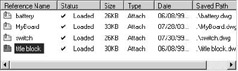
Although you can use individual commands for each manipulation of a referenced drawing, AutoCAD provides a manager-type dialog box – the Xref Manager (Figure 23.1.1a) – to help with Xrefs.
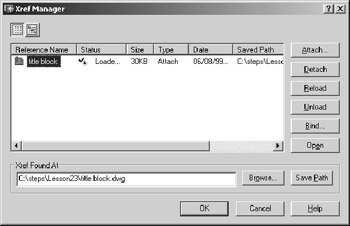
Figure 23.1.1a
Let's take a look.
-
AutoCAD allows you to view the items in the list box using either a List View (the default) or a Tree View. Toggle between types of views using the buttons in the upper left corner of the manager. (We'll use the default List View in this lesson).
-
In the list box, AutoCAD provides several columns of information:
-
The Reference Name is the file name of the referenced drawing.
-
The drawing's Status will fall into one of several categories:
-
Loaded simply means that the drawing is currently attached.
-
An Unloaded reference will be removed from the primary drawing once the Xref Manager is closed. This isn't a permanent condition. The reference remains intact and may be reloaded as desired.
-
A Reloaded designation means that AutoCAD will reload that reference when the Xref anager closes.
-
An Unreferenced drawing is attached to the primary drawing but has been erased.
-
A drawing that no longer resides in the folder from which it was originally referenced (or in the search path defined in the Options dialog box) is marked in the tatus column as Not Found.
-
If AutoCAD can't read the referenced drawing, it marks it as Unresolved.
-
Xrefs can be nested. An Orphaned drawing was nested into a reference that is unreferenced, unloaded, or not found.
Note The Project File Search Path is defined on the Files tab of the Options dialog box (shown). Pick the "+" beside the Project File Search Path listing to see the folders AutoCAD will search. To add a folder, select the Project File Search Path listing and pick the Add… button. AutoCAD will add a listing, and you must type in the desired name.
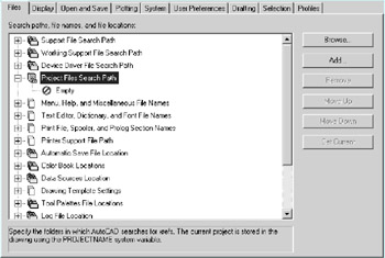
Then pick the plus beside the new project name, double-click on the Empty slot, and select the folder you wish to add to the search path.
Warning: Don't make changes in the Options dialog box without first consulting the CAD guru on your project.
-
-
The Size column indicates the size of the referenced drawing.
-
You can either Attach or Overlay a reference (see the Type column). An attached drawing will go with the primary drawing if another drawing references it; an overlaid drawing won't (more on this in Section 23.1.4).
-
The Date column indicates when the referenced drawing was last modified.
-
The Saved Path column is a bit misleading. The path refers to the location of the drawing when it was originally referenced but not necessarily where the reference is found. Let me explain.
When AutoCAD begins a drawing, it searches for referenced drawing in the Saved Path location. If it doesn't find it there, it searches the Project File Search Path defined in the Options dialog box. Then it searches the folder in which the current drawing resides. It'll use the first file it finds with the appropriate name regardless of its location. But it won't change the information in the Saved Path.
-
-
Down the right side of the Xref Manager (Figure 23.1.1a), you'll find six buttons.
-
The Attach… button begins the XAttach command.
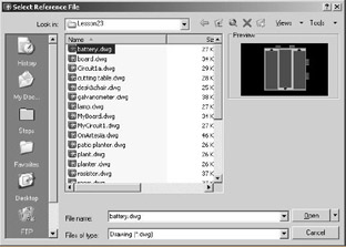
The XAttach command begins with a Windows standard Select File dialog box. There you'll follow the path to the file you wish to reference. Once you've selected a file and picked the Open button (on the Select File dialog box), AutoCAD presents the External Reference dialog box (Figure 23.1.1c).
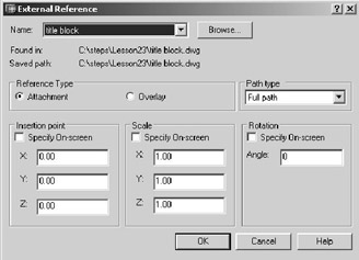
Figure 23.1.1c-
The Name control box indicates the file you're attaching. You may pick the Browse… button to select another file.
-
In the Reference Type frame, tell AutoCAD if you want your reference to be an Attachment or Overlay.
-
The Path type provides three options to make location of the reference a bit easier.
-
Using Full path (the default) means that AutoCAD will use the full path (drive & location) when searching for the reference.
-
The Relative path option tells AutoCAD that the referenced file may be located in a subfolder of the folder in which the primary drawing is located. Relative paths won't work if the referenced drawing is on another drive, and the primary drawing must be saved before this option is available.
-
No path means that the referenced drawing must be located in the same folder as the primary drawing or in a path identified in the Project File Search Path in the Options dialog box.
-
-
The Insertion, Scale, and Rotation frames are identical to their counterparts on the Insert dialog box (called by the Insert command – see Lesson 18).
-
-
Use the Detach button to remove references to the selected drawing. AutoCAD will detach the drawing when the Xref Manager closes. (Note: You can't detach a nested reference. You must detach its primary drawing.)
-
Unload a drawing to remove a reference that you may want to use later. Unloading doesn't permanently remove the reference from the drawing, but it does remove it from display.
-
The Reload button marks the selected file for reloading when the Xref Manager closes. Use this button to update a reference without having to reopen your primary drawing, or to display an unloaded drawing.
-
Use the Bind button to permanently attach a reference to a primary drawing. (This isn't the same as the XBind command, which we'll discuss in Section 23.1.3.) AutoCAD presents the Bind Xrefs dialog box (Figure 23.1.1d – next page) with two options.
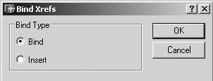
Figure 23.1.1dAs referenced information, dependent symbols are identified by the name of the referenced drawing followed by a bar and the symbol's name (i.e., board|slots is the slots layer on the referenced board drawing). The two options in the Bind Xrefs dialog box determine how Xref dependent symbols will be treated.
Note Dependent symbols are the layers, blocks, text styles, dimension styles, and linetypes that are part of a referenced drawing. To be available in the primary drawing, these symbols require that the referenced drawing be attached.
-
Binding a referenced drawing causes AutoCAD to rename the dependent symbol but retain the referenced drawing's name in the new name. Thus, the board|slots layer will become board$0$slots. This approach means that you'll always be able to trace where the symbol originated. [If the board$0$slots already exists, the number between the dollar signs increases (board$1$slots, board$2$slots, etc.).]
-
Inserting a referenced drawing changes the referenced drawing into a block with the name of the referenced drawing becoming the name of the block. Dependent symbols become a part of the drawing but drop the name of the referenced drawing (i.e., board|slots becomes slots).
-
-
The Open button opens the selected reference for editing in a new AutoCAD window when the Xref Manager closes. This provides a simple way to edit the reference (we'll look at another way later in this lesson).
-
-
The Xref Found At frame indicates where the selected drawing was found when AutoCAD loaded. This is where AutoCAD actually found the drawing and may not be the same as the saved path.
-
Use the Browse… button to select a different copy of the selected drawing to reference.
-
Use the Save Path button to redefine the saved path of the selected drawing to that shown in the Xref Found At box.
-
Whew! That was a lot of material to cover! Let's try our hands at Xref-ing.
Here's the scenario for this lesson:
Your employer is developing a new product – a kit designed to help children learn about electricity. The kit will contain a circuit board where the child can attach a battery pack, switches, lights, resistors, and a galvanometer (kids love those big scientific words). The kit must be capable of creating any of several different wiring layouts.
Your job is to lay out some wiring diagrams of things the child can build using the objects listed. You have the initial board and component designs from the engineer, but some of these objects may change as the project develops. You don't have time to wait for engineering (what a surprise!), so you'll begin your layouts now using Xrefs so you can easily modify the component designs as they develop.
| Note | You can also access the Xref Manager by selecting Xref Manager…, or the XAttach command by selecting External Reference… on the Insert pull-down menu. |
Do This: 23.1.1.1 Working with Xrefs
-
Start a new drawing using the Start template found in the C:\Steps\Lesson23 folder.
-
Save the drawing as MyBoard in the C:\Steps\Lesson23 folder.
-
Follow these steps.
TOOLS
COMMAND SEQUENCE
STEPS

External Reference Button
Command: xr
1. We'll begin by referencing our title block. Enter the Xref command by typing xref or xr at the command prompt. Alternately, you can pick the External reference button on the Reference toolbar.

2. AutoCAD presents the Xref Manager. Pick the Attach… button.
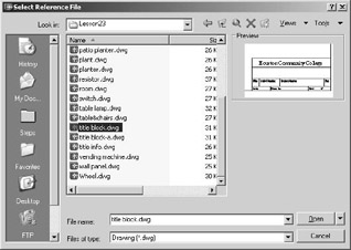
3. AutoCAD presents the elect Reference File dialog box. Select the title block.dwg file in the C:\Steps\Lesson23 folder. (Double-click on the file name or pick the Open button to continue.)
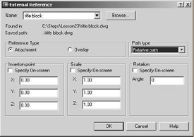
4. AutoCAD presents the External Reference dialog box. Be sure the selections match those shown.
-
Use the Attachment eference Type and a Relative path.
-
Remove the checks from the boxes in the three lower frames.
Pick the OK button to continue.
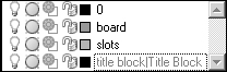
5. Check the Layer control box. Notice that AutoCAD has added the layer title block|Title Block. (The other layers were part of the template.) This is the layer on which the title block was created and has been referenced with the drawing. Notice that the layer is gray – you can turn it off, freeze it, lock it, or plot it; but it can't be made current. Nor can you draw on this layer, as it isn't actually part of the primary drawing.
6. Draw the board shown in Figure 23.1.1.1.6a.
-
The rectangle's corners are at coordinates 1,1 and 8.5,9.
-
The fillets are ½".
-
There are 15 rows and 14 columns of slots.
-
The board is on the board layer.
-
The slots are on the slots layer.
-
The slots are 3/16"dia., ½" apart, and begin at coordinate 1.5,1.5.
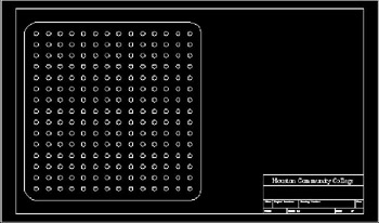
Figure 23.1.1.1.6a
Command: qsave
Command: close
7. Save the drawing and close it.

8. Start a new drawing using the Start template found in the C:\Steps\Lesson23 folder. Save the drawing as MyCircuit1 in the C:\Steps\Lesson23 folder.
9. Repeat Steps 1 to 4, but this time, reference the MyBoard.dwg you created earlier in this lesson.

Command: close
10. Save the drawing.

External Reference Attach Button
Command: xa
11. Using the XAttach command, we'll attach the battery and switch drawings.
Begin by entering the xattach command by typing xattach or xa at the command prompt. Alternately, you can pick the External Reference Attach button on the Reference toolbar. (You'll notice that this procedure is identical to the one we used to attach the MyBoard.dwg file except that we skip the Xref Manager.)
12. Repeat Step 3, but this time select the battery.dwg file.

13. Insert the file at coordinates 2.5,4.
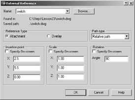
14. Repeat Steps 11 through 13 to insert the switch.dwg file at coordinates 2.5,5.5. Be sure to insert this file at 90°. Your board looks like Figure 23.1.1.1.14a.
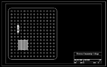
Figure 23.1.1.1.14a
Command: qsave
15. Save the drawing but don't exit.
-
Notice the two pairs of wire connections on both the switch and the battery. Our engineers haven't decided where to put the single required pair, so they've created two for now. We have a fair idea which ones they'll eventually use, but we don't want to change the actual component drawings yet. We can, however, alter the reference to show only those connections we want to show.
23.1.2 Removing Part of a Reference – the XClip Command
You'll use a tool called XClip to remove part of a reference drawing. The command sequence looks like this:
Command: xclip (or xc)
Select objects: [select the reference(s) to clip]
Select objects: [enter]
Enter clipping option
[ON/OFF/Clipdepth/Delete/generate Polyline/New boundary] <New>: [tell AutoCAD what you want to do – accept the default to clip a reference]
Specify clipping boundary:
[Select polyline/Polygonal/Rectangular] <Rectangular>: [tell AutoCAD what type of clipping boundary you wish to use]
-
The ON/OFF toggles work on clipping windows. They determine whether AutoCAD will present only those portions of the referenced drawing visible through the clipping window (ON) or the entire referenced drawing (OFF).
-
Clipdepth allows you to set the front/back clipping planes of three-dimensional objects. A two-dimensional boundary must exist before you can define front or back clip points. Identify the clip points by coordinate or distance from the two-dimensional clipping boundary.
Note AutoCAD provides a system variable to allow you to see the boundary even when it isn't a polyline. The system variable is XClipFrame. A setting of 0 (the default) means the boundaries will be hidden. A setting of 1 will show the boundaries. AutoCAD provides a button – External Reference Clip Frame – on the Reference toolbar to help you toggle the system variable on and off.
-
Use Delete to remove a boundary.
-
Generate Polyline will automatically draw a polyline along the clipping boundary. Again, a boundary must exist before AutoCAD can generate the polyline.
-
New boundary (the default) permits you to identify a new clipping boundary.
The next line of options ([Select polyline/Polygonal/ Rectangular] <Rectangular>:) offers some choices for how to create the new boundary.
-
Use the Select polyline option to use an existing polyline to define the boundary. The polyline doesn't have to be closed, but it must consist of only straight-line segments (no arcs) and must not intersect itself. (To create a "round" clipping boundary, use a polygon with a large number of sides.)
-
Use the Polygonal option to create a multisided or nonlinear shape for a boundary (much like using a poly-window to create a selection set).
-
Use the Rectangular option (the default) to use a window to define the clipping boundary.
We'll remove the extra wire connectors from the views of our battery and switch.
| Note | You can also access the XClip command on the Modify pull-down menu. Follow this path: Modify – Clip – Xref |
Do This: 23.1.2.1 Clipping Xrefs
-
Be sure you're still in the MyCircuit1.dwg file. If not, please open it now.
-
This exercise is easier if you zoom in around the battery and switch.
-
Follow these steps.
TOOLS
COMMAND SEQUENCE
STEPS

External Reference Clip Button
Command: xc
1. Enter the XClip command by typing xclip or xc at the command prompt. Alternately, you can pick the External Reference Clip button on the Reference toolbar.
Select objects:
Select objects: [enter]
2. Select the battery and confirm the selection.
Enter clipping option
[ON/OFF/Clipdepth/Delete/ generate Polyline/New boundary] <New>: [enter]
3. Accept the default New boundary option.
Specify clipping boundary:
[Select polyline/Polygonal/ Rectangular] <Rectangular>: [enter]
4. Tell AutoCAD that you'll create a Rectangular clipping boundary (the default).
Specify first corner: _endp of
5. Place the first corner at the lower right corner of the battery (use OSNAPs).
Specify opposite corner: 2.5,4.25
6. … and the opposite corner at the coordinates indicated. AutoCAD clips the reference, and the battery now looks like Figure 23.1.2.1.6a. (Note that you haven't actually modified the battery, just how much of it you can see through the reference window.)

Figure 23.1.2.1.6a7. Repeat Steps 1 to 6 to clip the side connections from the switch. Your board looks like Figure 23.1.2.1.7a.
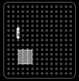
Figure 23.1.2.1.7a
Command: xr
8. Have you noticed that the title block affects your ability to zoom in and out on the board with ease? Let's remove it temporarily while we work on our board.
Open the Xref Manager.
9. Notice that all the referenced drawings are now listed – even the nested title block drawing (remember, it was part of the MyBoard drawing).
Select the title block as indicated.

10. Pick the Unload button. Notice that the Status of the title block reference changes to Unload.

11. Pick the OK button to complete the procedure.

Command: z
12. Zoom extents now to see that, although it's still attached, the title block drawing is no longer loaded into our MyCircuit1 drawing.

Command: qsave
13. Save the drawing but don't exit.
23.1.3 Xrefs and Dependent Symbols
AutoCAD allows two methods of permanently attaching referenced drawing data to the primary file – Binding and Xbinding. You'll use the Bind button on the Xref Manager to permanently attach, or bind, an entire referenced drawing to the primary drawing. We discussed this in Section 23.1.1 and will demonstrate it in Section 23.4. But you can also attach parts (specific dependent symbols) of the referenced drawing individually to the primary drawing. The command for this is Xbind, and it presents the Xbind dialog box (Figure 23.1.3a).
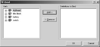
Figure 23.1.3a
The Xbind dialog box is one of AutoCAD's easiest. Simply select the dependent symbol you wish to bind in the Xrefs frame, pick the Add-> button, and OK your changes!
Let's try one. The battery drawing has a wire layer and a times text style; we'll add these to our primary file.
| Note | You can also access the Xbind command on the Modify pull-down menu. Follow this path: Modify – Object – External Reference – Bind… |
Do This: 23.1.3.1 Xbinding Dependent Symbols
-
Be sure you're still in the MyCircuit1.dwg file. If not, please open it now.
-
Follow these steps.
TOOLS
COMMAND SEQUENCE
STEPS

External Reverence Bind Button
Command: xb
1. Enter the Xbind command by typing xbind or xb at the command prompt. Alternately, you can pick the External Reference Bind button on the Reference toolbar.
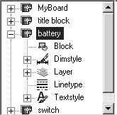
2. AutoCAD presents the Xbind dialog box (Figure 23.1.3a). Pick the "+" beside the battery reference. AutoCAD presents a lost of dependent symbol categories. Categories with symbols available for binding have a "+" beside them.
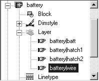
3. Pick the "+" beside the Layer category, and then select the battery|wire layer.
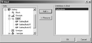
4. Pick the Add-> button. Notice that the battery|wire layer disappears from the Xrefs frame and appears in the Definitions to Bind frame.

5. Pick the OK button to complete the command.
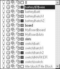
6. Check the Layer control box. Notice that the battery|wire layer has been replaced with battery$0$wire. You can now use this layer as you would any other layer in the primary drawing.
7. Repeat Steps 1 to 5 to bind the battery|times text style to the primary drawing. [Check your success by looking in the Style Name control box in the Text Style dialog box to be sure you've the battery$0$times style (Figure 23.1.3.1.7a).
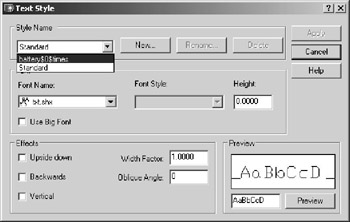
Figure 23.1.3.1.7a
Command: qsave
8. Save the drawing but don't exit.
23.1.4 Unloading, Reloading, and Overlaying Xrefs
In Exercise 23.1.2.1, we unloaded the title block reference to make our work easier. All we had to do to accomplish this was to select the drawing to unload (title block) and then pick the Unload button in the Xref Manager. Unloading a reference can speed work by reducing regeneration time. And as we saw, unloading a reference can remove unnecessary, distracting, and even obstructing objects from the display. But eventually, you'll probably have to reload the unloaded reference.
Reloading an unloaded reference is as easy as unloading it. Simply select the drawing to reload and pick the Reload button in the Xref Manager. We'll reload the title block in our next exercise.
But first, let's consider the Attach versus Overlay types of reference. Consider the diagram in Figure 23.1.4a.
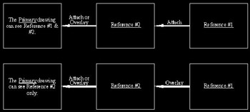
Figure 23.1.4a
As you can see, the Overlay type of reference is effective only when used on a nested reference. In other words, overlaying a reference into the primary drawing won't affect the nested reference's visibility. To hide the nested reference, it must be overlaid into the drawing being referenced by the primary drawing. We'll see this in our next exercise.
This is what we'll do: We'll reload our title block (which is nested into the MyBoard drawing reference). [MyBoard (Reference #2 in the diagram) references title block (Reference #1) using the Attach type of reference; therefore, we can see it from the primary drawing (MyCircuit1).] In our exercise, we'll change the reference type between MyBoard and title block and see how that affects MyCircuit1.
Let's begin.
Do This: 23.1.4.1 Reloading and Overlaying References
-
Be sure you're still in the MyCircuit1.dwg file. If not, please open it now.
-
Follow these steps.
TOOLS
COMMAND SEQUENCE
STEPS

Command: xr
1. Call the Xref Manager.

2. Select the title block reference and then pick the Reload button.

3. Pick the OK button to complete the procedure. Notice that the title block is again visible. (If necessary, zoom all to see it.)

Command: qsave
4. Save the drawing.

Command: xr
5. Open Xref Manager again.

6. Select the MyBoard reference and pick the Open button.

7. Pick the OK button to close the Xref Manager.
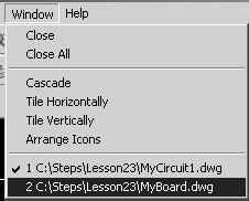
8. To make it active, select the MyBoard file from the Windows pull-down menu.

Command: xr
9. Call the Xref Manager.
10. Double-click on the word Attach in the Type column (next to title block). Notice that it changes to Overlay. (It's just that easy to change the reference type.)

11. Pick the OK button to close the Xref Manager.

Command: qsave
12. Save and close the drawing.
13. AutoCAD presents a bubble message (Figure 23.1.4.1.13a) telling you that a referenced drawing has changed. Pick on the name of the drawing (MyBoard). AutoCAD opens the Xref Manager.
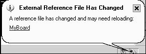
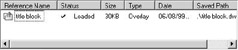
Figure 23.1.4.1.13a 14. Notice that MyBoard has a note in the Status column telling you that it needs to be reloaded. Select MyBoard and pick the Reload button.

15. Pick the OK button to complete the procedure. Notice that the title block disappears. An overlaid reference won't show in the primary drawing.
16. Repeats Steps 5 through 15, but this time, set the type of reference to Attach.

Command: qsave
17. Save the drawing but don't exit.
|
| < Day Day Up > |
|
EAN: 2147483647
Pages: 96