21.2 Using Tiled Viewports
|
| < Day Day Up > |
|
Use tiled viewports in Model Space (what you might consider "normal" drawing space) to enhance your ability to see several parts of the drawing at once. This ability will become particularly important when drawing in three dimensions. You can place a three- dimensional view of the object in one viewport while drawing on a single, two-dimensional plane (one side of the object) in another.
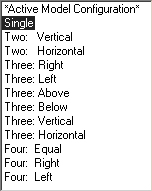
Create tiled viewports using the Viewports dialog box (Figure 21.2a). Access the dialog box using either the Viewports or VPorts command.
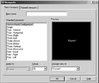
Figure 21.2a
Let's look at our options.
The names of the two tabs indicate their function; use New Viewports to create new viewports and Named Viewports to activate or set current a saved viewport configuration.
We'll begin with the New Viewports tab.
-
Place a name or title in the New name text box at the top if you wish to save a current configuration. (Don't use a name if you won't need to save the configuration.) You'll be able to recall your configuration later using the Change view to control box (lower-right center of the dialog box) or the Named Viewports tab.
-
The Standard viewports list box provides a list of the more common viewport setups. Select each and see the configuration in the Preview frame.
-
Once you've selected a viewport configuration, you can choose to apply your selection to the Display or the Current Viewport using the Apply to control box. Using the Display option will replace the drawing's current configuration with the new selection. Using the Current Viewport option will place the new configuration inside the currently active viewport. This is how you customize your viewports.
-
The Setup control box offers two choices: 2D or 3D.
-
The 2D option will place the drawing's current view in each of the viewports.
-
The 3D option will create the viewports using standard 3D views (top, front, side, isometric).
-
Once selected, you can adjust the view using display commands (Zoom, Pan, View).
-
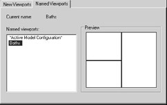
The Named Viewports tab (Figure 21.2b) presents the Named viewports list box and a Preview frame.
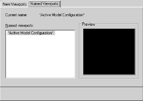
Figure 21.2b-
The Named viewports list box offers the names of any viewport configurations that have been saved. You can set a viewport configuration current by selecting its name and picking the OK button.
-
The Preview frame allows you to see the setup of the selected viewport configuration.
-
Let's experiment a bit.
| Note | You can also access the Viewports dialog box by selecting it from the pull-down menus. Follow this path: View – Viewports – New Viewports … |
Do This: 21.2.1 Working with Tiled Viewports
-
Open the flr-pln21a.dwg file in the C:\Steps\Lesson21 folder. The drawing looks like Figure 21.2.1a.
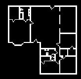
Figure 21.2.1a -
Follow these steps.
TOOLS
COMMAND SEQUENCE
STEPS

Display Viewports Dialog Button
Command: vports
1. We'll begin by creating some viewports. Enter the Viewports command by typing viewports or vports at the command prompt. Alternately, you can pick the Display Viewports Dialog button on either the Viewports or the Layout toolbar.
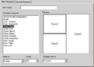
2. Select the Three: Right configuration. Notice the Preview window.

3. Pick the OK button to continue. Your drawing looks like Figure 21.2.1.3a.
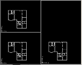
4. Place your cursor into each of the viewports. Notice that only the right (active) viewport presents crosshairs. Other (inactive) viewports present a cursor arrow. Activate a viewport by placing the cursor in the desired viewport and picking once with the left mouse button. Notice that you can activate only one viewport at a time.
Notice also that each viewport contains the UCS icon. You can manipulate each viewport separately as though it were your entire drawing screen.
5. Be sure the right viewport is active. (Place the cursor in the right viewport and pick once with the left mouse button.)

Command: z
5. Zoom extents. Notice that the Zoom command affects only the active viewport. Then Pan (if necessary) to center the floor plan in the viewport.
6. Pick anywhere in the upper left viewport to activate it.

Command: z
7. Zoom in around the master bath. The viewport will look like Figure 21.2.1.7a.
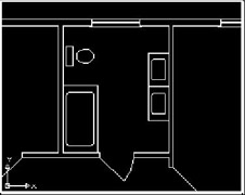
Figure 21.2.1.7a8. Now activate the lower left viewport.

Command: z
9. Zoom in around the common bath. The viewport will look like Figure 21.2.1.9a.
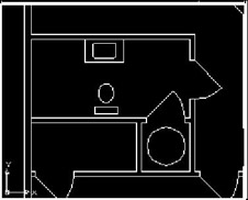
Figure 21.2.1.9a
Command: co
10. Let's place a tub in the common bath. Enter the Copy command.
Select objects:
Specify base point or displacement, or [Multiple]: _endp of
11. Pick once in the upper left viewport to activate it; then select the bathtub. Select the lower left endpoint of the tub as your base point.
Specify second point of displacement or <use first point as displacement>: _endp of
12. Pick once in the lower left viewport to activate it, and then place the tub in the lower left corner of the bathroom. Your screen now looks like Figure 21.2.1.12a. Notice that the changes are reflected in the right viewport as well as the lower left.
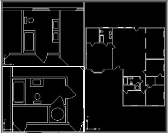
Figure 21.2.1.12a
Command: qsave
13. Remember to save the drawing occasionally.

Command: vports
14. Now let's save our viewport configuration. Open the Viewports dialog box.

15. Enter the name Baths in the New name text box.

16. Pick the OK button to complete the procedure.

Command: vports
17. Now let's reset the screen to a Single viewport. Reopen the Viewports dialog box.
18. Select the Single configuration and then pick the OK button to continue. AutoCAD presents a single viewport displaying the view of the current (lower left) viewport.

Command: z
19. Zoom extents.

Command: vports
20. Now restore the Baths configuration. Open the Viewports dialog box.
21. Pick the Named Viewports tab and select the Baths configuration in the Named viewports list box.
22. Pick the OK button to complete the command. AutoCAD presents the Baths configuration (see Figure 21.2.1.12a).

Command: qsave
23. Save the drawing but don't exit.
You can see the benefits of using viewports when manipulating several smaller parts of your drawing at one time. But when we consider the limitations of tiled viewports, we can see that they were designed as drawing aids, not plotting tools.
Some things to remember about tiled viewports include:
-
Tiled viewports were designed for use in Model Space.
-
Tiled viewports are not objects and won't plot. Your plot will show only the view in the active viewport.
-
Only one viewport is active at a time. This means that you can draw only in one viewport at a time, but you can activate a new viewport transparently (or while using another command).
-
The active viewport will show crosshairs while inactive viewports will show a cursor. Place the cursor in the viewport you wish to activate and click once to activate it.
-
Layers behave universally in tiled viewports. You can't freeze or thaw a layer just for one viewport as you can with floating viewports. (You'll see how to use layers in floating viewports in Lesson 22.)
-
While you can control the number and position of tiled viewports, you can't easily control the size. You can't control the shape at all (all tiled viewports are rectangular).
-
You can create viewports within viewports, but you should consider the size of the viewports and the size of your monitor before attempting this.
-
Manipulation of viewports doesn't affect the actual drawing.
To see how you can use viewports to assist in plotting a drawing that uses multiple scales, we'll take a look at floating viewports in Section 21.4. But first, we must set up our Paper Space environment.
| Note | You'll often see the term Paper Space written as paperspace. Both refer to the same thing, though paperspace is generally a programmer's term. |
|
| < Day Day Up > |
|
EAN: 2147483647
Pages: 96