17.8 Exercises
|
| < Day Day Up > |
|
-
Use the following information to create the drawing in Figure 17.8.1d. Save the drawing as MyTee in the C:\Steps\Lesson17 folder.
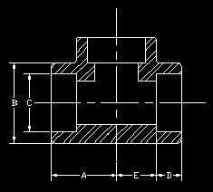
Figure 17.8.1a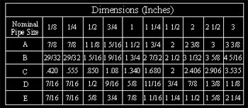
Figure 17.8.1b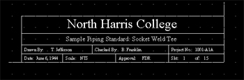
Figure 17.8.1c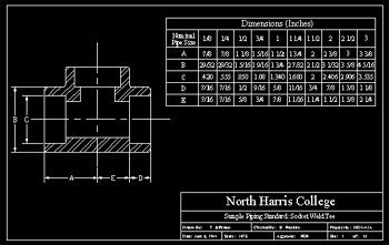
Figure 17.8.1d: Socket Weld Tee1.1
Layer Information:
Layer Name
Color
Linetype
0
7 (white)
Continuous
Border
5 (blue)
Continuous
Cl
3 (green)
Center
Dim
5 (blue)
Continuous
Hatch
32
Continuous
Marker
6 (magenta)
Continuous
Ob
1 (red)
Continuous
Text
6 (magenta)
Continuous
1.2
Limits: 0,0 to 17,11
1.3
Grid spacing = 1/4"
1.4
Text sizes = 3/8", 1/4", 3/16", 1/8"
1.5
Font: Times New Roman
1.6
Hatching information
1.6.1
Pattern = ANSI32
1.6.2
Scale = 1"
1.6.3
Angle = 0
-
Start a new drawing from scratch.
2.1
Create the following setup:
2.1.1
Use a 1½"=1'-0" scale on an A-size sheet of paper (8½x11)
2.1.2
Grid: 1" (snap as needed)
2.1.3
These layers:
Layer
Name
Color Linetype
0
7 (white)
Continuous
Cl
6 (magenta)
Center2
Const
1 (red)
Continuous
Obj1
4 (cyan)
Continuous
Obj3
1 (red)
Continuous
Text
2 (yellow)
Continuous
2.2
Use this information for the Grade hatching:
Pattern: EARTH
Scale: 8.0000
Angle: 45
2.3
Use this information for the sand hatching:
Pattern: AR-SAND
Scale: 0.5000
Angle: 0
2.4
Use the Times New Roman font. Large text should plot at ¼"; small text should plot at 1/8".
2.5
Create the Exterior Slab drawing shown in Figure 17.8.2a. Save it as MySlab in the C:\Steps\Lesson17 folder.
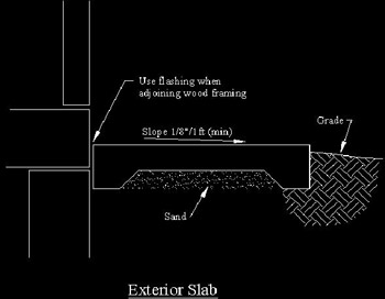
Figure 17.8.2a: Exterior Slab -
Start a new drawing from scratch. Using the same information you used in the Exterior Slab drawing in Exercise 2, create the Concrete Pier Footing drawing in Figure 17.8.3a.
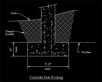
Figure 17.8.3a: Concrete Pier Footing3.1
Use this information to hatch the concrete:
Pattern: AR-CONC
Scale: 0.5000
Angle: 0
3.2
Save the drawing as MyFooting in the C:\Steps\Lesson17 folder.
-
Open the Cabin-hatch.dwg file in the C:\Steps\Lesson17 folder. Use the following information to complete the drawing. The completed elevations are shown in Figures 17.8.4a & b. (See if you can add a chimney on your own.)
4.1
Create these additional layers:
Layer Name
Color
Linetype
Hatch1
85
Continuous
Hatch2
22
Continuous
Hatch3
44
Center
Hatch4
214
Continuous
4.2
Hatching information:
4.2.1
Doors:
Pattern: AR-RROOF
Scale = ¼"
Angle = 90°
Layer = Hatch34.2.2
Roof:
Pattern: AR-RSHKE
Scale = 1/16"
Angle = 0°
Layer = Hatch34.2.3
Facade:
Pattern: AR-BRELM
Scale = 1/8"
Angle = 0°
Layer = Hatch24.2.4
Curtains:
Pattern: STARS
Scale = 1"
Angle = 90°
Layer = Hatch44.2.5
Gables:
Pattern: ANSI31
Scale = 1"
Angle = 45°
Layer = Hatch24.2.6
Doorknobs are on the Hatch1 layer.
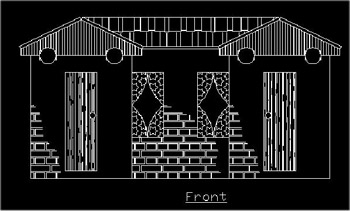
Figure 17.8.4a: Front Elevation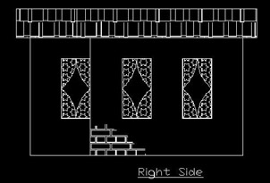
Figure 17.8.4b: Side Elevation -
Using what you've learned, create the drawings in Figures 17.8.5a to 17.8.5h. The grid, where shown, is 2".
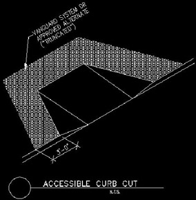
Figure 17.8.5a: Curb CutThanks to Tilco Vanguard of Snohomish, Washington and Jon Julnes for allowing us to use this drawing.
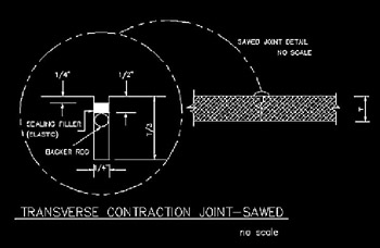
Figure 17.8.5b: Transverse Contraction Joint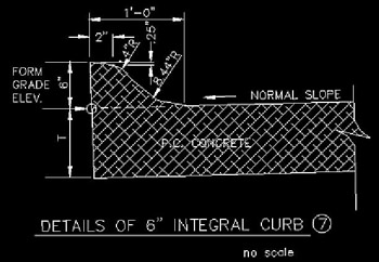
Figure 17.8.5c: Integral Curb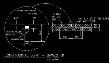
Figure 17.8.5d: Longitudinal Joint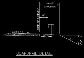
Figure 17.8.5e: Guardrail Detail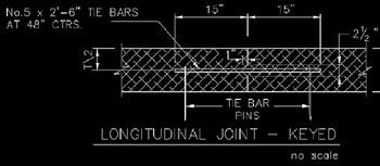
Figure 17.8.5f: Longitudinal Joint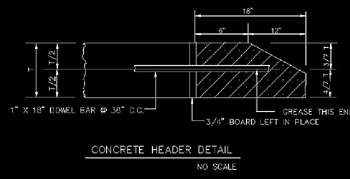
Figure 17.8.5g: Concrete Header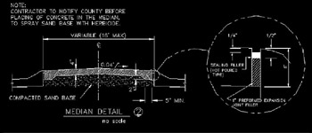
Figure 17.8.5h: Median DetailSpecial thanks to Randy Behounek at the Sarpy County Surveyors Office in Papillion, Nebraska for permission to use Figures 17.8.5b to 17.8.5h drawings.
-
Using what you've learned, create the drawing shown in Figure 17.8.6a.
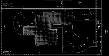
Figure 17.8.6a: Plot Plan
|
| < Day Day Up > |
|
EAN: 2147483647
Pages: 96
- Structures, Processes and Relational Mechanisms for IT Governance
- An Emerging Strategy for E-Business IT Governance
- Linking the IT Balanced Scorecard to the Business Objectives at a Major Canadian Financial Group
- A View on Knowledge Management: Utilizing a Balanced Scorecard Methodology for Analyzing Knowledge Metrics
- The Evolution of IT Governance at NB Power