10.3 From Outlines to Solids - The Solid and Donut Commands
10.3 From Outlines to Solids “ The Solid and Donut Commands
Tired of drawing stick figures (outlines)?
The only tool we've seen thus far for drawing objects with width is the polyline. This tool can create most of the objects on which we need to show width. But wait there are others! There are even tools that are easier to use than the polyline! Do you find that hard to believe? Read on!
Two easy tools for showing a solid surface in the 2- dimensional world are the Solid command and the
Donut command. With the Solid command, you can fill triangular areas. With the Donut command, you can fill round areas.
Let's start with the Solid command. The sequence follows :
Command: solid (or so )
Specify first point: [pick the first corner of the area to fill]
Specify second point: [pick the second corner of the area to fill]
Specify third point: [pick the third corner of the area to fill “ if there are four corners or more, select the corner nearest the first corner]
Specify fourth point or <exit>: [AutoCAD repeats the third and fourth corner until you end the command by hitting enter]
Specify third point: [enter]
Let's try it.
| Note | This command is also available in the Draw pull-down menu. Follow this path :
|
Do This: 10.3.1 Creating Solids
-
Be sure you're still in the mea-div drawing in the C:\Steps\Lesson10 folder.
-
Set the OBJ1 layer current.
-
Follow these steps.
Tools
Command Sequence
Steps

Command: os
1. Set the Running OSNAP to Node and Intersection . Clear all other settings.

2D Solid Button
Command: so
2. Enter the Solid command by typing solid or so . Alternately, you can pick the 2D Solid button on the Surfaces toolbar.
Specify first point: [select point 1]
Specify second point: [select point 2]
Specify third point: [select point 3]
Specify fourth point or <exit>: [enter]
Specify third point: [enter]
3. Select points 1, 2, and 3 as shown in Figure 10.3.1.3a. Then hit enter twice to exit the command.
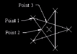
Figure 10.3.1.3a: Command: so
4. Repeat Step 4 for each of the points of the star. Your drawing now looks like Figure 10.3.1.4a.

Figure 10.3.1.4a:
Command: qsave
5. Save your drawing but don't exit.
You see that drawing solids isn't difficult. Try drawing a rectangle next to the star, and then placing a solid inside. Pick your corners first in clockwise direction. Notice the hourglass shape of the solid (Figure 10.3a).

Figure 10.3a:
Now undo that and create your solid, picking the points in the order shown in Figure 10.3b.
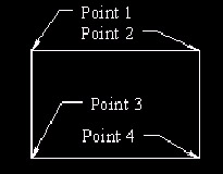
Figure 10.3b:
Notice the difference? You should always reverse Points 3 and 4 from the direction taken from Point 1 to Point 2 (that's, work in triangles ) in order to create a full solid, as shown in Figure 10.3c.

Figure 10.3c:
Donuts are polylines and are as easy to draw as solids. But the Donut command does ask a couple questions.
Command: donut (or do )
Specify inside diameter of donut <0'-0 1/2">: [set the diameter of the donut hold]
Specify outside diameter of donut <0'-1">: [set the outer diameter of the donut]
Specify center of donut or <exit>: [place the donut]
Specify center of donut or <exit>: [enter to complete the command]
The prompts are self-explanatory, so let's look at donuts in action.
| Note | This command is also available in the Draw pull-down menu. Follow this path:
|
Do This: 10.3.2 Using Donuts
-
Be sure you're still in the mea-div drawing in the C:\Steps\Lesson10 folder.
-
Follow these steps.
Tools
Command Sequence
Steps
No Button Available
Command: do
1. Enter the Donut command by typing donut or do at the command prompt. There is no toolbar button for this command.
Specify inside diameter of donut <0'-0 1/2">:
2. Set the inside diameter to
Specify outside diameter of donut <0'-1">: 2.25
3. and the outside diameter to 2.25 .
Specify center of donut or <exit>:
4. Place the center of donut at the node in the center of the star.
Specify center of donut or <exit>: [enter]
5. Hit enter to complete the command. Your drawing looks like Figure 10.3.2.5a.

Figure 10.3.2.5a:Command: [enter]
6. Let's place some other donuts. Repeat the command.
Specify inside diameter of donut <0'-0">: .25
Specify outside diameter of donut <0'-2 1/4">: .5
7. Make the inside diameter .25 and the outside diameter .5 .
Specify center of donut or <exit>:
8. Place donuts at the nodes at each of the points of the star. Hit enter to complete the command. Your drawing looks like Figure 10.3.2.8a.

Figure 10.3.2.8a: Command: qsave
9. Save your drawing but don't exit.
I must admit that my piping profession offered little opportunity to use solids or donuts. Still, had I been using a computer at the time, these commands would have been quite handy when I was designing those little houses that Santa sits in down at the mall!
| Note | Solids and donuts can cause a bit of a slowdown in regeneration time. They can also suck the ink right out of your plotter! In its infinite wisdom, AutoCAD provided a way to save time and plotter ink. Until you're ready for that final plot, set your Fillmode system variable to , then regenerate the drawing to see the results (see figure at right). AutoCAD hides the filled area of solids and replaces the filled area of donuts with wireframing (more on wireframing in the 3D text). Set the Fillmode back to 1 for the final plot. (Note: The Fillmode system variable controls the fill on polylines as well.)  |
- Step 1.1 Install OpenSSH to Replace the Remote Access Protocols with Encrypted Versions
- Step 3.2 Use PuTTY / plink as a Command Line Replacement for telnet / rlogin
- Step 4.7 Using Public Key Authentication for Automated File Transfers
- Step 6.1 Port Forwarding
- Step 6.2 Using Port Forwarding Within PuTTY to Read Your E-mail Securely