8.3 Editing Polylines - The PEdit Command
8.3 Editing Polylines “ The PEdit Command
If you thought drawing polylines was fun, you're in for a real treat now! Remember that second tier of options? The PEdit command has one, as well, and several smaller third tiers! Sort of makes you want to go back to the board, doesn't it? But to encourage you, let me just say that you'll probably never need the second (or third) tier “ or at least only rarely in the 2-dimensional world.
| Note | In the 3-dimensional world, it'll often be easier to edit a polyline. When you get there, it'll be useful if you already know how to add or move a vertex (the "corners" within a polyline). We'll see how to do that here, but you probably won't need it for a while. |
Two-dimensional polylines are such that it's often easier to erase and redraw than it's to edit. Still, you should be familiar with the PEdit command for those benefits that it does provide. These include the ability to change the width of the polyline and to join several polylines into a single object.
The PEdit command sequence looks like this:
Command: pedit (or pe )
Select polyline or [Multiple]: [select the polyline(s) to edit]
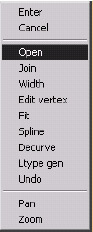
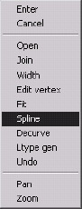
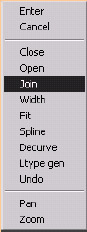
Enter an option [ Open /Join/Width/Edit vertex/Fit/Spline/Decurve/Ltype gen/Undo]: tell AutoCAD how you want to edit the polyline]
This sequence takes us up to the first tier of options. Let's stop here to examine them.
-
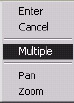
Use the Multiple option to edit more than one polyline at a time. (Note: The Edit vertex option isn't available during multiple polyline editing sessions.)
-
The Open option appears if a closed polyline is selected at the Select polyline prompt. Conversely, a Close option appears if an open polyline is selected. The Open option removes the last line segment “ the one that closed the polyline. The Close option adds a polyline segment between two open endpoints.
-
The Join option enables you to join one polyline to another to form one large polyline. We'll see how this works in Section 8.3.2.
-
The Width option allows you to modify the polyline's width.
-
Fit and Spline will soften corners into curves. This was once the tool of choice for drawing contour lines for topographical maps. However, AutoCAD now provides a Spline command that was specifically designed for drawing contour lines (more on this in Lesson 11). The difference between Fit and Spline is that, although Fit will create curves that go through each point on the polyline, Spline 's curves go through only the first and last point.
The rest of the points "pull" the curve but don't insist that the curve touch each point.
-
Decurve removes all curves on the polyline whether put there as Arcs , Fits , or Splines .
Note The system variable Splinetype controls the amount of curve caused by the Spline option. A setting of 5 will cause a more pronounced curve (called a Quadratic B-spline) that's actually tangent to the original polyline. The default setting of 6 causes a softer, less pronounced curve (a Cubic B- spline). There are only the two settings available.
-
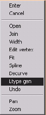
Ltype gen regulates the placement of dashes and spaces in linetypes . Let me make this as simple as possible. Through some fairly complicated mathematics, AutoCAD normally balances dashes and spaces in a line so that the amount of solid line at both ends is the same. If the length of the line doesn't allow enough room for the dashes and spaces defined by the linetype, no spaces are shown. When turned on , Ltype gen calculates the placement of dashes and spaces for the overall polyline. When turned off (the default), the placement is calculated for each individual line segment within the polyline. This will become clearer in our exercise.
-
By now you're familiar with the Undo option. It undoes the last modification made within the PEdit command.
We'll look in some detail at the Edit vertex option later in this lesson. But let's try an exercise on what we've learned so far.
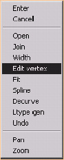
| Note | In addition to the command line and toolbar, you can find the PEdit command by selecting Object , and then Polyline , in the Modify pull-down menu. The various options of the PEdit command are also available on the cursor menu once the PEdit command has been entered. |
Do This: 8.3.1 Working with Simple Polyline Editing Tools
-
Open the MyPline drawing you created earlier in this lesson. If this drawing isn't available, open the Pline drawing in the C:\Steps\Lesson08 folder.
-
Follow these steps.
Tools
Command Sequence
Steps

Edit Polyline Button
Command: pe
1. Enter the PEdit command by typing pedit or pe . Alternately, you can pick the Edit Polyline button on the Modify II toolbar.
Select polyline or [Multiple]:
2. Select the outer polyline.
Enter an option [Open/Join/Width/Edit vertex/Fit/Spline/Decurve/Ltype
gen/Undo]: o
3. Let's start with the Open option. Type o or pick Open on the cursor menu. Your drawing will look like Figure 8.3.1.3a.

Figure 8.3.1.3a: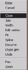
Enter an option [Close/Join/Width/Edit vertex/Fit/Spline/Decurve/Ltype gen/Undo]: c
4. Notice how the prompt has changed from Open to Close . Use the Close option. Notice that the figure is closed and looks like it did when you started.
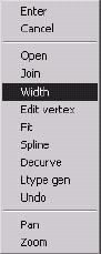
Enter an option [Open/Join/Width/Edit vertex/Fit/Spline/Decurve/Ltype gen/Undo]: w
5. Select the Width option.
Specify new width for all segments: 1/32
6. AutoCAD asks for a new width. Enter 1/32. Notice the difference in the figure. It now looks like Figure 8.3.1.6a.

Figure 8.3.1.6a: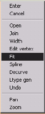
Enter an option [Open/Join/Width/Edit vertex/Fit/Spline/Decurve/Ltype gen/Undo]: f
7. Note where the vertices (corners) are on the figure, then select the Fit option. Your drawing looks like Figure 8.3.1.7a. (Notice that the polyline still goes through the vertices.)

Figure 8.3.1.7a:Enter an option [Open/Join/Width/Edit vertex/Fit/Spline/Decurve/Ltype gen/Undo]: u
8. Undo the last modification.
9. Now try the Spline option. Your drawing now looks like Figure 8.3.1.9a. (Notice the differences between Fit and Spline .)

Figure 8.3.1.9a: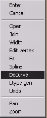
10. Decurve the polyline. It looks like Figure 8.3.1.10a.

Figure 8.3.1.10a:Enter an option [Open/Join/Width/Edit vertex/Fit/Spline/Decurve/Ltype gen/Undo]: u
Enter an option [Open/Join/Width/Edit vertex/Fit/Spline/Decurve/Ltype gen/Undo]: u
11. Undo the last two modifications. The drawing will look as it did in Step 6.
Enter an option [Open/Join/Width/Edit vertex/Fit/Spline/Decurve/Ltype gen/Undo]: [enter]
12. Exit the command.

Command: props
13. Change the linetype of the polyline to Center2 . (Refer to Section 6.1.2 for help loading the linetype if it isn't already loaded, and Section 6.1.5 for help changing it.) Your drawing looks like Figure 8.3.1.13a.
Notice that there are no dashes and spaces showing in the smaller arcs.
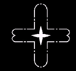
Figure 8.3.1.13a: Command: pe
14. Repeat the PEdit command.
Select polyline or [Multiple]:
15. Select the same polyline.
Enter an option [Open/Join/Width/Edit vertex/Fit/Spline/Decurve/Ltype gen/Undo]: l
16. Select the Ltype gen option.
Enter polyline linetype generation option [ON/OFF] <Off>: on
17. Turn it On . Notice the change in the drawing (Figure 8.3.1.17a) “ dashes and spaces now show in the smaller arcs.

Figure 8.3.1.17a:Enter an option [Open/Join/Width/Edit vertex/Fit/Spline/Decurve/Ltype gen/Undo]: [enter]
18. Exit the command.
Command: props
19. Return the linetype to ByLayer .
As I mentioned earlier, the Join option allows you to join two (or more) polylines together to make a single polyline. You control how this is done. It works like this:
Command: pedit (or pe )
PEDIT Select polyline or [Multiple]: m [use the Multiple option to select more than one polyline]
Select objects: [select the polylines you wish to join together]
Select objects: [hit enter to complete the selection]
Enter an option [Close/Open/Join/Width/Fit/ Spline/Decurve/Ltype gen/Undo]: j [select the Join option]
Join Type = Extend [AutoCAD tells you what type of join it'll perform]
Enter fuzz distance or [Jointype] <0.0000>: .5 [tell AutoCAD how far apart the polylines may be]
1 segments added to polyline [AutoCAD tells you how many segments it has added to the polyline]
Enter an option [Close/Open/Join/Width/Fit/ Spline/Decurve/Ltype gen/Undo]: [hit enter to complete the command]
You must make two decisions when joining polylines “ the Join Type and the fuzz distance .
-
Fuzz distance refers to how much distance separates the polylines. AutoCAD will only join polylines whose endpoints fall within the distance you specify “ that's, the distance you specify is the outer limit of the polylines' proximity to each other. You can actually use this option to your advantage “ joining only those polylines whose endpoints fall within a certain distance or even touch each other (use a 0.0000 fuzz distance).
-
The Jointype option will present the following prompt:
Enter join type [Extend/Add/Both] <Extend>:
Select the type of joining you would like between your polylines.
-
Extend , the default, will extend or trim the polylines as necessary to form the joint.
-
Add will add polyline segments between the endpoints of the selected polylines.
-
When using the Both option, AutoCAD will extend or trim the polylines whenever possible to form the joint; where this isn't possible, as in the case of parallel polylines, it'll add a polyline segment.
Let's try an exercise to see the Join option in action.
Do This: 8.3.2 Joining Polylines
-
Open the Join drawing in the C:\Steps\Lesson08 folder. It looks like Figure 8.3.2a.
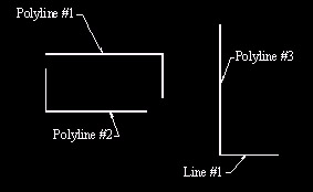
Figure 8.3.2a: -
Follow these steps.
Tools
Command Sequence
Steps
Command: pe
1. Enter the PEdit command.
Select polyline or [Multiple]: m
Select objects:
Select objects: [enter]
2. Use the Multiple option, and select Polyline #1 and Polyline #2 .
Enter an option [Close/Open/Join/Width/ Fit/Spline/Decurve/Ltype gen/ Undo]: j
3. Use the Join option.
Join Type = Extend
Enter fuzz distance or [Jointype] <0.0000>: .6
4. The grid in this drawing is 0.5. The proximity of one set of endpoints is less than 0.6; the proximity of the other set is greater that 0.6. Set the fuzz distance to 0.6 .
2 segments added to polyline
Enter an option [Close/Open/Join/Width/ Fit/Spline/Decurve/Ltype gen/Undo]: [enter]
5. AutoCAD tells you how many segments it added to the polyline. Hit enter to complete the command. You now have a single polyline consisting of four segments; it looks like Figure 8.3.2.5a.
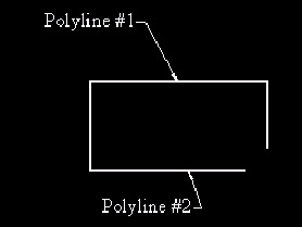
Figure 8.3.2.5a: Command: pe
Select polyline or [Multiple]: m
Select objects:
6. Let's repeat this procedure using Polyline #3 and the Line . Repeat Steps 1 and 2, this time selecting these objects.
Convert Lines and Arcs to polylines [Yes/No]? <Y> [enter]
7. Because one of the objects you selected was not a polyline, AutoCAD asks if you'd like to convert it to one. Hit enter to accept the offer. (This is how you convert from a line to a polyline.)
Enter an option [Close/Open/Join/Width/ Fit/Spline/Decurve/Ltype gen/Undo]: j
8. Again, use the Join option.
Join Type = Extend
Enter fuzz distance or [Jointype] <0.6000>:
1 segments added to polyline
Enter an option [Close/Open/Join/Width/ Fit/Spline/Decurve/Ltype gen/Undo]: [enter]
9. Reset the fuzz distance to and complete the command.
The objects don't look any different; but if you try to erase one, you'll notice that both area selected. Both segments are now part of a single polyline!
Command: close
10. Close the drawing without saving.
We've just about covered the first tier of options in the PEdit command. The only remaining option is the key to the next tier “ Edit vertex . As a beginning CAD operator in a 2-dimensional world, you'll rarely find the need to edit a vertex. But the option comes in quite handy for very complex polylines and 3- dimensional polylines. Choosing Edit vertex will result in the following list of second-tier options:
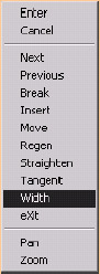
Enter a vertex editing option
[Next/Previous/Break/Insert/Move/Regen/Str aighten/Tangent/Width/eXit] <N>:
You'll notice that, when you enter this level of the PEdit command, a small "X" appears on the polyline you're editing (Figure 8.3a). The X is a locator to let you know which vertex is being edited.
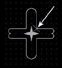
Figure 8.3a:
-
The Next (default) and Previous options move the locator forward and backward to each vertex around the polyline.
-
Use the Break option just as you used the Break command “ to remove part of a polyline.
-
Insert enables you to define a new vertex on the polyline and Straighten allows you to remove an existing vertex.
-
Move , of course, enables you to move a vertex, thus reshaping the polyline.
-
In the event that too much editing causes the polyline to display oddly on your screen, you can Regen just the polyline while within the editing session. This saves you from having to leave the command, regen the drawing, and then return to the PEdit command.
-
The Tangent option allows you to assign a tangent direction for AutoCAD to use when it fits the polyline (with the Fit option on the upper tier).
-
The Width option on the first tier of choices allowed you to change the width for the entire polyline. The Width option on the second tier allows you to change the width for a specific segment of the polyline.
Let's look at some of these options.
Do This: 8.3.3 More Complex Polyline Editing Tools
-
If you're not already in the MyPline or Pline drawing, please open one of them now. Refer to Figure 8.3.3a for this exercise. (I've shown the numbers of the vertices on all of the graphics in this exercise to make it easier for you to follow.)
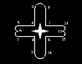
Figure 8.3.3a: -
Follow these steps.
Tools
Command Sequence
Steps
Command: pe
1. Enter the PEdit command.
Select polyline or [Multiple]:
2. Select the outer polyline.
Enter an option [Open/Join/Width/Edit vertex/Fit/Spline/Decurve/Ltype gen/Undo]: e
3. Use the Edit vertex option to access the next tier of options.
Enter a vertex editing option
[Next/Previous/Break/Insert/Move/Regen/ Straighten/Tangent/Width/eXit] <N>: [enter]
4. Reposition the locator to point 2. Notice the default option is N . This is the Next option, so just hit enter to reposition the locator.
Enter a vertex editing option
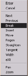
[Next/Previous/Break/Insert/Move/Regen/ Straighten/Tangent/Width/eXit] <N>: b
5. Select the Break option.
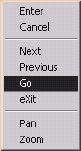
Enter an option [Next/Previous/Go/eXit] <N>: [enter]
6. Notice that AutoCAD drops to a third tier of options. Next and Previous work as they do in the second tier. Go executes the option that dropped you to this level (in this case, the Break option). Exit to leave this level without executing the level two option. Hit enter to accept the Next default. The locator will move to point 3.
Enter an option [Next/Previous/Go/eXit] <N>: g
7. Use the Go option to execute the Break option. The segment between points 2 (where you began the Break option) and 3 (where you're now) is removed as shown in Figure 8.3.3.7a.
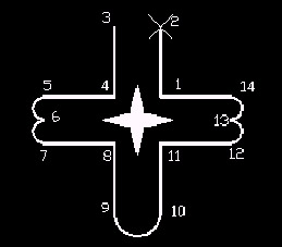
Figure 8.3.3.7a: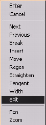
Enter a vertex editing option
[Next/Previous/Break/Insert/Move/Regen/ Straighten/Tangent/Width/eXit] <N>: x
Enter an option [Close/Join/Width/Edit vertex/Fit/Spline/Decurve/Ltype gen/Undo]: [enter]
8. Use the eXit option to return to the primary tier, and then hit enter to leave the command.
Command: [enter]
9. Repeat Steps 1, 2, and 3.
Enter a vertex editing option
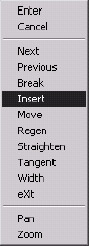
[Next/Previous/Break/Insert/Move/Regen/ Straighten/Tangent/Width/eXit] <N>: i
10. Now let's Insert a vertex.
Notice that AutoCAD provides a rubber band (a line from the currently selected vertex) to help guide you.

Specify location for new vertex: _mid of
11. Place the new vertex midway between points 3 and 4 (Figure 8.3.3.11a). Use your OSNAPs! Notice the locator appears at this new point.
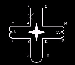
Figure 8.3.3.11a: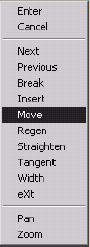
Enter a vertex editing option
[Next/Previous/Break/Insert/Move/Regen/ Straighten/Tangent/Width/eXit] <N>: m
Specify new location for marked vertex: @1<180
12. Now move the new vertex a single unit to the left. Your drawing now looks like Figure 8.3.3.12a.
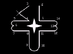
Figure 8.3.3.12a:Enter a vertex editing option
[Next/Previous/Break/Insert/Move/Regen/ Straighten/Tangent/Width/eXit] <N>: p
13. Now we'll remove the new vertex. Return the locator to point 3 (use the Previous option).
Enter a vertex editing option
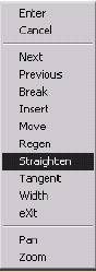
[Next/Previous/Break/Insert/Move/Regen/ Straighten/Tangent/Width/eXit] <P>: s
14. Use the Straighten option.
Enter an option [Next/Previous/Go/eXit] <N>: [enter]
Enter an option [Next/Previous/Go/eXit] <N>: [enter]
Enter an option [Next/Previous/Go/eXit] <N>: g
15. Hit enter until the locator moves to point 4. Then use Go to execute the Straighten option. The new vertex disappears and the drawing appears as it did in Step 7.
Enter a vertex editing option
[Next/Previous/Break/Insert/Move/Regen/ Straighten/Tangent/Width/eXit] <P>: w
16. Now use the Width option to change the width of a single line segment.
Specify starting width for next segment <0.0625>:
Specify ending width for next segment <0.0000>: .125
17. Set the starting width to and the ending width to 1/8 . Your drawing will look like Figure 8.3.3.17a.
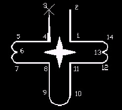
Figure 8.3.3.17a:18. Follow Step 8 to exit the PEdit command.

Command: quit
19. Exit the drawing without saving your changes.
Note One other aspect of the PEdit command is its effect on non-polyline lines and arcs. You've seen what happens when you select a line or arc at the Select polyline prompt. AutoCAD will ask if you want to turn it into a polyline. This is the conversion method lines or arcs to polylines.
To convert polylines to lines or arcs, simply use the Explode command (or use the Explode button on the Modify toolbar). AutoCAD prompts:
Select objects:
The prompt will repeat until you hit enter to confirm completion of the selection set. Be aware, however, that only a polyline can show WYSIWYG width. An exploded polyline becomes a line or arc and loses its width.