8.1 Using the PLine Command for Wide Lines and Multi-Segmented Lines
You've already used two commands that make use of polylines “ Rectangle and Polygon; so you've some idea of how polylines behave. Each group of lines acts as a single object when modified or manipulated. With Rectangle , you even saw that you could control the line width. Now we'll see how to create objects with a little more freedom than these commands allowed “ by using the PLine command.
One of AutoCAD's more difficult commands, PLine contains several options. We'll look at each, but the basic sequence is
Command: pline (or pl )
Specify start point: [select a starting point]
Current line-width is 0.0000
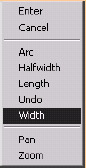
Specify next point or [Arc/Halfwidth/Length /Undo/Width]: select the next point]
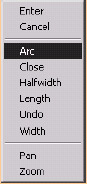
Specify next point or [Arc/Close/Halfwidth/ Length/Undo/Width]: [you can continue to create line segments or hit enter to complete the command]
The options appear more intimidating than they actually are.
-
Close works just like it does with the Line command. That is, it closes the polyline. But remember, unlike lines, the entire polyline will be treated as a single unit.
-
Halfwidth and Width do the same thing. These are your options for telling AutoCAD how wide to make the polyline. Width is how wide you want the polyline, whereas Halfwidth , of course, is half of the width. Why two options to achieve the same end? AutoCAD redundancy again! Each of these options provides its own prompts. The Halfwidth prompts are
Specify starting half-width <0.0000>:
Specify ending half-width <0.0000>:
The Width prompts are the same, but ask for width rather than halfwidth. Notice that the starting and ending widths can be set separately. This'll come in handy when creating arrowheads, as we'll see in our first exercise.
-
Length allows you to enter the length of a line segment. The user who ignores this option in favor of one of AutoCAD's many other methods of defining line length (direct distance, Cartesian coordinates, polar tracking, etc.) will probably be happier . The Length option provides this prompt:
Specify length of line:
-
Undo will do just that. Here at the PLine prompt, it undoes the last segment drawn. (Of course, if undo is entered at the command prompt after the polyline has been drawn, the entire command is undone.)
-
Notice that AutoCAD repeats the list of options, always with the Specify next point option as the default. This makes it simple to continue drawing “ selecting points “ until finished while making all the other options available for each line segment. In other words, you can change the width, close the polyline, or switch to an arc at any time during the creation process.
-
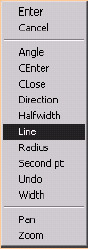
Arc allows you to create polyline arcs “ that's, sequential arcs or arcs with width. The Arc option provides a second tier of prompts that behave remarkably like the options of the Arc command:
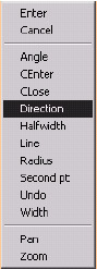
Specify endpoint of arc or [Angle/CEnter/CLose/Direction/ Halfwidth/Line/Radius/Second pt/ Undo/Width]:
-
The Angle option allows you to specify an included angle to define the arc. To more easily understand this, think of pieces of a circle. A circle is 360 °. 45 ° would be 1/8 of the circle, so specifying an angle of 45 ° will tell AutoCAD to draw 1/8 of a circle. AutoCAD will prompt as it did in the Arc command:
Specify included angle: [specify the angle]
Specify endpoint of arc or [CEnter/ Radius]: [tell AutoCAD how you want to draw the arc]
-
The CEnter option allows you to specify the center point of the arc followed by an Angle , the Length of the arc, or the Endpoint of the arc. Again, pline arc prompts resemble the Arc command:
Specify center point of arc:
Specify endpoint of arc or [Angle/ Length]:
-
The CLose option in this tier will close the polyline using an arc. You can use this method to create circles with line-width.
-
AutoCAD normally draws an arc in a counterclockwise direction. Once you draw an arc using the PLine command, AutoCAD reverses direction but stays in the Arc mode until told to switch back to Lines or to CLose (or exit) the PLine command. If you wish to draw a series of arcs in the same direction “ like tiles on a roof “ the Direction option allows you to specify the direction of the next arc. AutoCAD prompts
Specify the tangent direction for the start point of arc:
Specify endpoint of the arc:
-
Halfwidth and Width provide a way to change the width of the polyline from within the Arc option. AutoCAD prompts the same way it did for these options in the first tier of PLine options.
-
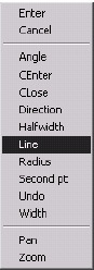
The Line option returns you to the first tier of PLine options. From there, you can continue the polyline or exit the command.
-
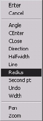
One of the easier options is the Radius option. With this, AutoCAD allows you to specify the radius of the arc followed by the Angle or endpoint . Radius options are
Specify radius of arc:
Specify endpoint of arc or [Angle]:
-
You can draw a three-point arc, just as you did with the Arc command, by using the Second pt option. AutoCAD prompts for the second point on the arc, then the endpoint , as seen here:
Specify second point on arc:
Specify end point of arc:
-
Undo performs just as it did in the upper tier.
-
The default option is simply to Specify endpoint of arc . When that's done, AutoCAD repeats the options until you either select the Line option or exist the command by hitting enter .
-
Do you see why we say this command is Beyond the Basics ? It took several pages to explain the various parameters of the PLine command. It's a powerful tool, but don't let the scope of the PLine command deter you from its use. Most students get the hang of it fairly quickly. Let's look at some of the options in an exercise.
| Note | In addition to the command line and toolbar, you can access the PLine command by selecting Polyline from the Draw pull-down menu. The various options of the PLine command are also available in the cursor menu once the PLine command has been entered. |
Do This: 8.1.1 Drawing with Polylines
-
Start a new drawing from scratch.
-
Set the grid to 0.5 and the grid snap to 0.25 . Turn on polar tracking.
-
Follow these steps.
Tools
Command Sequence
Steps

Polyline Button
Command: pl
1. Enter the PLine command by typing pline or pl . Alternately, you can pick the Polyline button on the Draw toolbar.
Specify start point: 6,5
2. Select a starting point at 6,5 .
Current line-width is 0.0000
Specify next point or [Arc/Halfwidth/Length /Undo/Width]: w
3. AutoCAD tells you what the Current line- width setting is, and then prompts you for the next step. Type w or pick Width on the cursor menu to change the line width.
Specify starting width <0.0000>: 1/16
4. Set the starting width to 1/16.
Specify ending width <0.0625>: [enter]
5. AutoCAD has set the ending width to match the starting width, but asks you if you want to change it. Hit enter to accept the setting.
Specify next point or [Arc/ Halfwidth/ Length/Undo/ Width]: @1.5<90
6. Draw the first line segment 1.5 units upward. Use coordinate entry or polar tracking.
Specify next point or [Arc/Close/Halfwidth/ Length/ Undo/Width]: a
7. Tell AutoCAD to draw an Arc next.
Specify endpoint of arc or
[Angle/CEnter/CLose/Direction/Halfwidth/ Line/Radius/Second pt/Undo/Width]: @1<180
8. Accept the endpoint of arc option and place the endpoint 1 unit to the left.
Specify endpoint of arc or
[Angle/CEnter/CLose/Direction/ Halfwidth/Line/Radius/Second pt/Undo/Width]: l
9. Select the Line option to return to the upper tier of options. (Note: Remember, AutoCAD isn't case-sensitive “ that's, it doesn't matter if you type a capital or small letter.)
10. Continue the polyline 1.5 units downward using polar tracking (you may need to toggle Polar on). At this time, your polyline will look like Figure 8.1.1.10a.

Figure 8.1.1.10a:Specify next point or [Arc/Close/ Halfwidth/ Length/Undo/Width]: @1.5<180
11. Continue 1.5 units to the left.
Specify next point or [Arc/Close/Halfwidth/ Length/ Undo/Width]: a
12. Use the Arc option again.
Specify endpoint of arc or
[Angle/CEnter/CLose/Direction/ Halfwidth/Line/Radius/Second pt/Undo/Width]: r
Specify radius of arc: .25
Specify endpoint of arc or [Angle]: [select a point one grid mark due south of the current point]
13. Draw the arc with a ¼ unit Radius downward.
Specify endpoint of arc or
[Angle/CEnter/CLose/Direction/ Halfwidth/Line/Radius/Second pt/Undo/Width]: d
14. Let's use the Direction option to repeat the arc.
Specify the tangent direction for the start point of arc:
15. Pick a point due west of the current point, as indicated in Figure 8.1.1.15a.
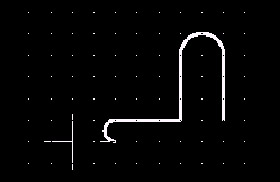
Figure 8.1.1.15a:Specify endpoint of the arc: @.5<270
16. Pick a point ½" to the south.
Specify endpoint of arc or
[Angle/CEnter/CLose/Direction/ Halfwidth/Line/Radius/Second pt/Undo/Width]: l
17. Return to the Line option.
Specify next point or [Arc/Close/ Halfwidth/Length/Undo/Width]:
18. Draw the line 1.5 units to the right using polar tracking. Your drawing now looks like Figure 8.1.1.18a.
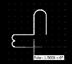
Figure 8.1.1.18a:19. Using the preceding details, see if you can complete the drawing. (Remember to type c to complete the polyline.) It'll look like Figure 8.1.1.19a.
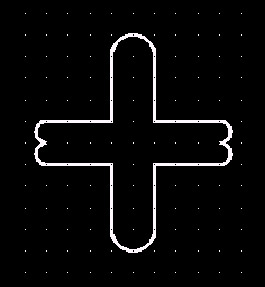
Figure 8.1.1.19a:
Command: z
20. And now let's try something completely different. Zoom in around the center of the object you just drew. Your screen should look like Figure 8.1.1.20a.
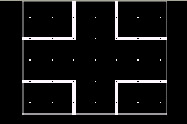
Figure 8.1.1.20a: Command: pl
21. Repeat the PLine command.
Specify start point: 4.75,4.5
22. Pick the starting point indicated at left.
Current line-width is 0.0625
Specify next point or [Arc/Halfwidth/Length /Undo/Width]: w
23. Tell AutoCAD you want to change the Width .
Specify starting width <0.0625>:
Specify ending width <0.0000>: .25
24. Set different starting and ending widths as indicated.
Specify next point or [Arc/Halfwidth/Length /Undo/Width]: @.5<0
25. Draw the line segment. Notice the arrowhead effect of your width settings.
Specify next point or [Arc/Halfwidth/Length /Undo/Width]: @.5<0
26. Continue the polyline. Now AutoCAD uses just the width setting of the endpoint of the last line segment drawn.
Specify next point or [Arc/Close/Halfwidth/ Length/ Undo/Width]: w
Specify starting width <0.2500>: [enter]
Specify ending width <0.2500>:
27. Change the Width again. Accept the 0.25 default of the starting width, but change the ending width back to .
Specify next point or [Arc/Close/Halfwidth/ Length/ Undo/Width]: @.5<0
Specify next point or [Arc/Close/Halfwidth/ Length/ Undo/Width]: [enter]
28. Complete the polyline. Your drawing will look like Figure 8.1.1.28a.
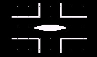
Figure 8.1.1.28a: Command: pl
29. Complete the drawing by placing a final polyline as shown in Figure 8.1.1.29a.
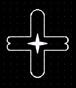
Figure 8.1.1.29a:Command: qsave
30. Save the drawing as MyPline to the C:\Steps\Lesson08 folder and exit.
Polylines can be a bit frightening at first because of the depth of the command. But don't let too many options prevent you from using one of AutoCAD's more useful tools.
We'll need to spend some time with the polyline editing tools; but first, let's take a bit of a break for something quite useful but a lot easier than polylines!