7.2 The Location and Number Group
7.2.1 Here to There: The Move Command
The Move command allows you to move one or more objects from one place to another. It has one of the easiest sequences to remember:
Command: move (or m )
Select objects: [select one or more objects] 1 found
Select objects: [enter to confirm completion of this selection set]
Specify base point or displacement: [pick a starting point “ or more simply, select the point at which you'll "pick up" the object]
Specify second point of displacement or <use first point as displacement>: [pick the target point “ the place where you'll put the object "down"]
The only options here involve the base point and the displacement .
-
The easiest way to explain base point is this: imagine the object(s) you're moving as a solid object sitting on a table. To move the object, you must first pick it up. The base point is the place you grab (a corner, an edge, the middle, etc.). The second point of displacement is where you put it down “ or the point at which you'll place the corner or edge (or whatever) you grabbed.
-
Notice the base point or displacement prompt. One mistake of even seasoned CAD operators is to read this a base point of displacement, which is wrong. They miss an easier way to move the object(s). Using the displacement method, the sequence would look like this:
Command: move (or m )
Select objects: [select one or more objects] 1 found
Select objects: [enter to confirm completion of this selection set]
Specify base point or displacement: 2,0
Specify second point of displacement or <use first point as displacement>: [enter]
Here we've moved the object(s) two units in the X- direction and zero in the Y-direction. We did this by entering a displacement in terms of X and Y rather than selecting a base point.
Do This: 7.2.1.1 Using the Move Command
-
Open Star.dwg in the C:\Steps\Lesson07 folder. The drawing looks like Figure 7.2.1.1a.

Figure 7.2.1.1a: -
Follow these steps.
Tools
Command Sequence
Steps

Move Button
Command: m
1. Enter the Move command by typing move or m at the command prompt. Alternately, you can pick the Move button on the Modify toolbar.
Select objects: Specify opposite corner: 13 found
Select objects: [enter]
2. Put a selection window around the entire circle and all it contents. Then hit enter to confirm completion of the selection set.

Specify base point or displacement: _qua of Specify second point of
displacement or <use first point as displacement>: @4<0
3. Select the lower quadrant of the circle. (You can select any point, but this one is convenient .) Use polar coordinates to move the circle 4 units to the right. Notice how the circle changes position.
Command: [enter]
4. We'll now use the displacement method to move it back. Repeat the command.
Select objects: Specify opposite corner: 13 found
Select objects:
5. Select the circle and all of its contents again, and then confirm the selection.
Specify base point or displacement: -4,0
Specify second point of displacement or <use first point as displacement>: [enter]
6. Rather than selecting a base point , type in the units you want to move. At the second point of displacement prompt, hit enter . Notice that the objects move back.
As you can see, there really isn't much to the Move command. But you do need to remember things like OSNAPs and Cartesian coordinates to ensure precision in your modifications.
7.2.2 Okay, Move It “ But Then Line It Up: the Align Command
A variation of the Move command, Align will move objects and then align them with something else. The command sequence is
Command: align (or al )
Select objects: [select the objects to be moved]
Select objects: [enter to confirm completion of the selection set]
Specify first source point: [this is the first point where you "grab" the objects]
Specify first destination point: [this is where you put the first grabbed point]
Specify second source point: [this is a second point where you grab the objects “ you need at least two points so that you can align the objects]
Specify second destination point: [this is where you put the second grabbed point]
Specify third source point or <continue>: [use a third point to "flip" or mirror the object, or when aligning a 3-dimensional object; otherwise , hit enter to continue]
Scale objects based on alignment points? [Yes/No] <N>: [do you want to adjust the size of the object you're moving so that the grabbed points fit exactly on the destination points?]
Don't worry; it's not as complicated as it sounds.
Do This: 7.2.2.1 Using the Align Command
-
Open align.dwg in the C:\Steps\Lesson07 folder.
-
Follow these steps.
Tools
Command Sequence
Steps

Command: os
1. Turn on the endpoint Running OSNAP. Clear all other OSNAPs.
Command: al
2. Enter the Align command by typing align or al at the command prompt.
Select objects:
Select objects: [enter]
3. Select box 1 and the text inside. Confirm completion of the selection set.
Specify first source point: [select point 1a]
Specify first destination point: [select point 1b]
Specify second source point: [select point 2a]
Specify second destination point: [select point 2b]
Specify third source point or <continue>: [enter to continue]
4. Using the endpoint OSNAP, select the points as indicated in Figure 7.2.2.1.4a.
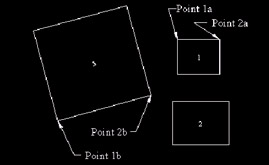
Figure 7.2.2.1.4a:Scale objects based on alignment points? [Yes/No] <N>: [enter]
5. Don't Scale objects this time.
Your drawing looks like Figure 7.2.2.1.5a.
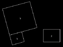
Figure 7.2.2.1.5a:Command: [enter]
Select objects:
Select objects: [enter]
6. Repeat the Align command. Let's try it again using box 2; this time, we'll scale the objects.
Specify first source point: [select point 1a]
Specify first destination point: [select point 1b]
Specify second source point: [select point 2a]
Specify second destination point: [select point 2b]
Specify third source point or <continue>: [enter to continue]
7. Select the points as indicated in Figure 7.2.2.1.7a.
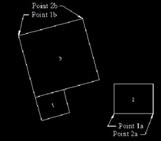
Figure 7.2.2.1.7a:Scale objects based on alignment points? [Yes/No] <N>: y
8. Scale the objects. Your drawing looks like Figure 7.2.2.1.8a.
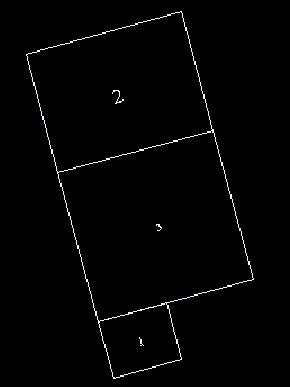
Figure 7.2.2.1.8a:
Command: qsave
9. Save and exit your drawing.
You can see, then, that the Align command is related to the Move command, although it's a bit more complex. You might say it's also related to two commands we haven't studied yet “ Rotate and Scale . Wow! Three commands in one! We'll look at the Rotate and Scale commands in Lesson 9.
7.2.3 The Copy Command: From One to Many
Another command that's related to Move , Copy has a command sequence that closely resembles the Move command sequence. Compare the following sequence with the Move sequence in Section 7.2.1.
Command: copy (or cp or co )
Select objects: [select one or more objects] 1 found
Select objects: [enter to confirm completion of this selection set]
Specify base point or displacement, or [Multiple]: [pick a starting ( grabbing ) point]
Specify second point of displacement or <use first point as displacement>: [pick a target point]
All the options are the same including the displacement method. But Copy provides one additional option “ Multiple . The Multiple option allows you to make more than one copy of an object(s).
Do This: 7.2.3.1 Using the Copy Command
-
Be sure you're in star.dwg in the C:\Steps\Lesson07 folder.
-
Follow these steps.
Tools
Command Sequence
Steps

Copy Button
Command: cp
1. Enter the Copy command by typing copy , cp , or co at the command prompt. Alternately, you can pick the Copy button on the Modify toolbar.
Select objects:
Select objects: [enter]
2. Put a selection window around the circle and all its contents. Then hit enter to confirm completion of the selection set.
Specify base point or displacement, or [Multiple]: _qua of
Specify second point of displacement or <use first point as displacement>: @4<0
3. Select the lower quadrant of the circle as the base point . Use polar coordinates to make a copy of the circle 4 units to the right. Your drawing looks like Figure 7.2.3.1.3a.
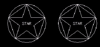
Figure 7.2.3.1.3a:
Command: e
4. Erase the new circle and its contents.
Command: co
5. Now let's make Multiple copies. Repeat the Copy command.
Select objects:
Select objects: [enter]
6. Select the objects as you did in Step 2.
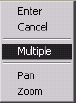
Specify base point or displacement, or [Multiple]: m
7. Type m or pick Multiple on the cursor menu for the Multiple option.
Specify base point: _cen of
8. Select the center of the circle (just to be different as the base point .
Specify second point of displacement or <use first
point as displacement>: @4<0
Specify second point of displacement or <use first point as displacement>: @8<0
Specify second point of displacement or <use first point as displacement>: @3<90
Specify second point of displacement or <use first point as displacement>: [enter]
9. Make three copies of the objects, as indicated. Your drawing will look like Figure 7.2.3.1.9a.
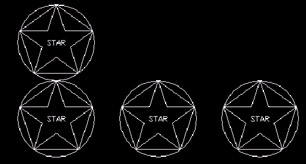
Figure 7.2.3.1.9a: Command: qsave
10. Save the drawing but don't exit.
As you can see, Copy , like Move , requires little effort to master. But the benefits can be wondrous in terms of time and effort saved.
| Note | Like so may other users, I was thrilled to find the Align command when AutoCAD included it with the software. Combining Move with Rotate was a stroke of genius. Unfortunately, there is no equivalent for the Copy command. Here again, AutoCAD has provided the ability to adjust its CAD package to your needs. I've included another Lisp routine in the C:\Steps\Lesson07 folder that will enable you to copy and rotate with one command. Loading Coprot.lsp will provide you with a command called CR . When accessed, you'll be prompted for the object(s) to be copied , the base point, the new location, and the desired rotation angle. AutoLISP will do the rest. |
- An Emerging Strategy for E-Business IT Governance
- Assessing Business-IT Alignment Maturity
- Linking the IT Balanced Scorecard to the Business Objectives at a Major Canadian Financial Group
- Measuring and Managing E-Business Initiatives Through the Balanced Scorecard
- Measuring ROI in E-Commerce Applications: Analysis to Action