6.9 Exercises
-
Create the drawing in Figure 6.9.1a using the following setup. Save the drawing as MyRemote in the C:\Steps\Lesson06 folder.
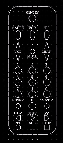
Figure 6.9.1a:Layer Names
Color
Linetype
Button
62
continuous
Dim
cyan
continuous
Obj
211
continuous
Text
yellow
continuous
Toggle
blue
continuous
Up-Down
211
continuous
1.1
Lower left limits: 0,0
1.2
Upper right limits: 6,10
1.3
Architectural units
1.4
Grid: ¼"
1.5
Snap: as needed
1.6
Font: Times New Roman
1.7
Text Height: 1/8"
-
Set up a drawing to be used in Lesson 9. Use the following parameters:
2.1
Lower left limits: 0,0
2.2
Upper right limits: 17,11
2.3
Architectural units
2.4
Grid: ½"
2.5
Snap: ½"
Layer Names
Color
Linetype
Border
magenta
continuous
Gradient
cyan
continuous
Ruler
red
continuous
Text
yellow
continuous
Cl
blue
center
2.6
Draw a border ¼" in from the limits on all sides (16 ½" x 10 ½").
2.7
Save the drawing as MyRuler to the C:\Steps\Lesson09 folder.
-
Using the MyBase3 template created in Lesson 1 (or the Base3 template in the Lesson01 folder), create the next three drawings (Figures 6.9.3a, 6.9.3b, and 6.9.3c). Save the drawings to the C:\Steps\Lesson06 folder using the name indicated in the title block of each. All drawings use the layers indicated in the Layers 1 drawing. (Hint: Change the snap setting as needed.)
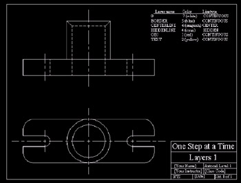
Figure 6.9.3a: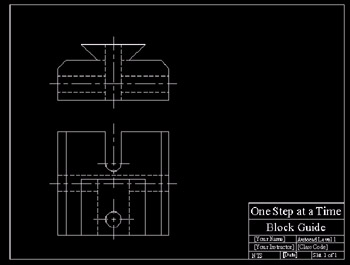
Figure 6.9.3b: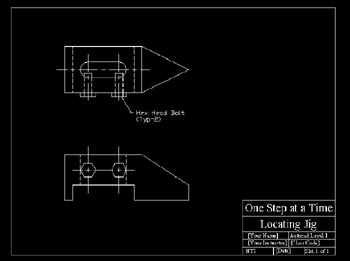
Figure 6.9.3c: -
Using what you know, create the drawings in Figures 6.9.4a through 6.9.4e. The grid on each, when shown, is ¼".
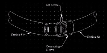
Figure 6.9.4a: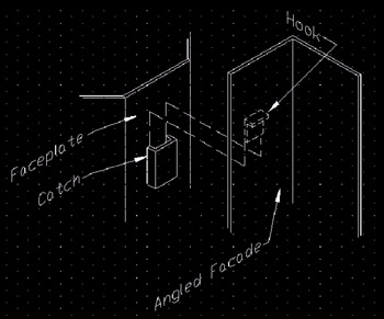
Figure 6.9.4b: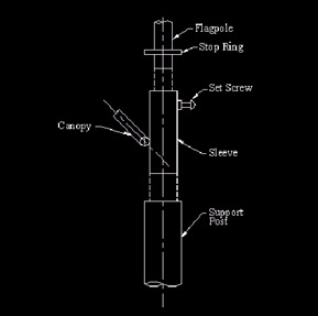
Figure 6.9.4c: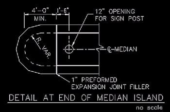
Figure 6.9.4d: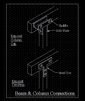
Figure 6.9.4e: -
Create the drawing in Figure 6.9.5a. The grid is 2". Use specific layers for each type of object being drawn.
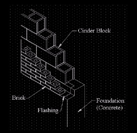
Figure 6.9.5a: