5.5 Putting It All Together
Let's try a project using what we've learned. We'll draw the Ring Stand Base shown in Figure 5.5a.
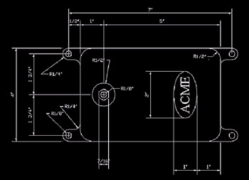
Figure 5.5a:
Do This: 5.5.1 Polygons, Arcs, and Circles “ The Project
-
Create a new drawing with the following setup:
-
Lower left limits: 0,0
-
Upper right limits: 17,11
-
Units: Architectural
-
Grid: ½
-
Snap: ¼
-
Textsize: 3/8
-
Font: Times New Roman
-
-
Follow these steps.
Tools
Command Sequence
Steps

Command: z
1. Zoom All to see the entire drawing.

Command: save
2. Save the drawing as MyStand to the C:\Steps\Lesson05 folder.

Command: l
3. Enter the Line command.
Specify first point: 4,2-1/2
Specify next point or [Undo]: @3<90
Specify next point or [Undo]: [enter]
4. Start at point 4,2 ½ and draw a 3" line upward.
Command: [enter]
Specify first point: 4-1/2,2
Specify next point or [Undo]: @5<0
Specify next point or [Undo]: [enter]
5. Repeat the Line command. Then draw the second line as indicated.
Command: [enter]
Specify first point: 4-1/2,6
Specify next point or [Undo]: @5<0
Specify next point or [Undo]: [enter]
6. Repeat the Line command. Then draw the third line.
Command: [enter]
Specify first point: 10,2-1/2
Specify next point or [Undo]: @3<90
Specify next point or [Undo]: [enter]
7. Repeat the Line command. Then draw the fourth line. Your drawing now looks like Figure 5.5.1.7a.
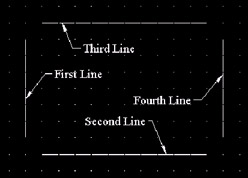
Figure 5.5.1.7a:
Command: os
8. Set the Running OSNAP to endpoint . Clear all other settings. (Remember to toggle the Running OSNAP On or Off using the F3 function key or the status bar toggle as needed!)

Command: a
9. Enter the Arc command.
Specify start point of arc or [Center]:
10. Select the endpoint of the second line nearest the fourth line.
Specify second point of arc or [Center/End]: c
11. Use the Center option.
Specify center point of arc:
12. Snap to the grid mark directly above the point you selected in Step 11.
Specify end point of arc or [Angle/chord Length]:
13. Select the lower endpoint of the fourth line.
Command: a
14. Repeat Steps 9 through 13 to draw the other three arcs. Your drawing now looks like Figure 5.5.1.14a.
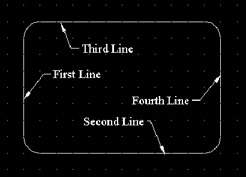
Figure 5.5.1.14a: Command: l
15. Repeat the Line command.
Specify first point:
Specify next point or [Undo]: @1<180
Specify next point or [Undo]: [enter]
16. (Refer to Figure 5.5.1.14a.) Draw a 1" line from the left endpoint of the second line in the 180 ° direction.
Command: l
17. Repeat Step 16 at all four corners. Your drawing will look like Figure 5.5.1.17a.
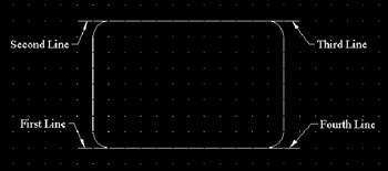
Figure 5.5.1.17a: Command: a
Specify start point of arc or [Center]: 3-1/2,2-1/2
18. (Refer to Figure 5.5.1.17a.) Now we'll draw an arc at the end of the first line. Start the command at the point indicated.
Specify second point of arc or [Center/End]: c
19. Use the Center option.
Specify center point of arc:
20. Select a point one snap down from the point selected in Step 18.
Specify end point of arc or [Angle/ chord Length]:
21. Select the endpoint of the first line.
Command: a
22. Repeat Steps 18 through 21 at the other four lines. Your drawing will look like Figure 5.5.1.22a.
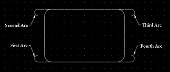
Figure 5.5.1.22a: Command: l
Specify first point:
Specify next point or [Undo]: @1/4<0
Specify next point or [Undo]: [enter]
23. Now add a ¼" line at the end of the first arc.
Repeat for each arc. Your drawing will look like Figure 5.5.1.23a.
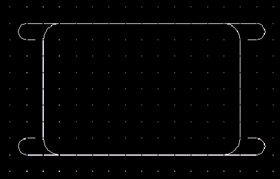
Figure 5.5.1.23a: Command: a
Specify start point of arc or [Center]: [select the endpoint of the line at the first arc]
24. Now draw arcs at the end of the new lines (refer to Figure 5.5.1.29a). We'll start at the lower left corner.
Specify second point of arc or [Center/ End]: e
25. Use the End option.
Specify end point of arc:
26. The endpoint is one snap up and one snap to the right.
Specify center point of arc or [Angle/ Direction/Radius]: d
27. Select the Direction option.
Specify tangent direction for the start point of arc:
28. Select a point to the right of the point selected in Step 24.
Command: a
29. Repeat Steps 24 through 28 for the other arcs. Your drawing looks like Figure 5.5.1.29a.
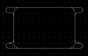
Figure 5.5.1.29a: Command: qsave
30. It's a good idea to save your drawing occasionally!

Command: c
31. Draw a circle in the center of the first anchor leg.

Specify center point for circle or [3P/2P/Ttr (tan tan radius)]: _cen of
32. Use the center OSNAP to locate the center of the first arc.
Specify radius of circle or [Diameter]: 1/8
33. Use a 1/8" radius for the circle.
Command: c
34. Repeat Steps 31 through 33 for each of the anchor legs. Your drawing will look like Figure 5.5.1.34a.
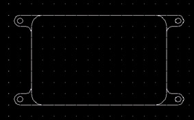
Figure 5.5.1.34a: Command: c
Specify center point for circle or [3P/2P/Ttr (tan tan radius)]: 5,4
Specify radius of circle or [Diameter] <0'-0 1/8">: 1/2
35. Now draw the 1" washer using the Circle command.
Command: c
Specify center point for circle or [3P/2P/Ttr (tan tan radius)]: 5,4
Specify radius of circle or [Diameter] <0'-0 1/2">: 1/8
36. Draw the ¼" bolt center using the Circle command.

Command: pol
37. Draw the bolt using the Polygon command.
Enter number of sides <4>: 6
38. Give it six sides.
Specify center of polygon or [Edge]: _cen of
39. Place it in the center of the last circle you drew.
Enter an option [Inscribed in circle/Circumscribed about circle] <I>: c
40. Since we've a dimension on the bolt from flat side to flat side, we'll draw the polygon around a circle with that diameter. Type c for Circumscribed .
Specify radius of circle: 7/32
41. Type in 7/32 (half the given diameter). Your drawing now looks like Figure 5.5.1.41a.
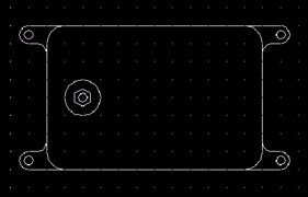
Figure 5.5.1.41a:
Command: el
42. Now let's draw the logo plate using the Ellipse command.
Specify axis endpoint of ellipse or [Arc/Center]: 8-1/2,3
43. Start at point 8 ½,3 .
Specify other endpoint of axis: @2<90
44. The ellipse is 2" along the long axis.
Specify distance to other axis or [Rotation]: @1/2<0
45. it's 1" along the short axis.
Command: dt
46. Add the ACME text to finish the project.
Current text style: "times" Text height: 0'-0 3/8"
Specify start point of text or [Justify/Style]: m
Specify middle point of text: 8-1/2,4
47. We'll middle-justify the text in the center of the ellipse.
Specify height <0'-0 3/8">: [enter]
48. If you set the textsize to 3/8 during the setup, it will default to that now. Otherwise, set it to 3/8 .
Specify rotation angle of text <0>: 90
49. Set the rotation angle so the text may be read from the bottom of the stand.
Enter text: ACME
Enter text: [enter]
50. Enter the text.
Command: qsave
51. Save your drawing. It should now look like the sample in Figure 5.5a.